CP-6-series Mechanical Reference.pdf - 第187页
7. Adjust the sliding portion of the cam lever to obtain the pick-up height if the measurements previously mentioned are out of the range specified on the previous page. 8. It is necessary to check the slider adjustment …
Pick-Up Height Adjustment
Ensure that the nozzle descends low enough to pick up a part set in the feeder. Confirm
that the mechanical valve movement creates a vacuum for part pick-up.
1. Set the 8 x 4 paper tape feeder (tape leaf removed) into the D1 location.
2. Move the feeder to station 1 with [SET] - [D Axis] - [1] - [CR].
3. Select [SET] - [MANUAL] - [I/O] and then press the EMERGENCY STOP button
to take the 200 V down to 100 V.
WARNING
• Turn off the 200 V servo power before carrying out this work.
• Exercise extreme caution when working on the machine if the cam is
not at its origin (0 deg.). Recoil of the cam axis can endanger the
operator.
4. Set the cam angle to 0°, then turn on the solenoid (Y020 PICK UP SOL ON) to
work the lever.
5. Use the cam handle to rotate the cam to 175°.
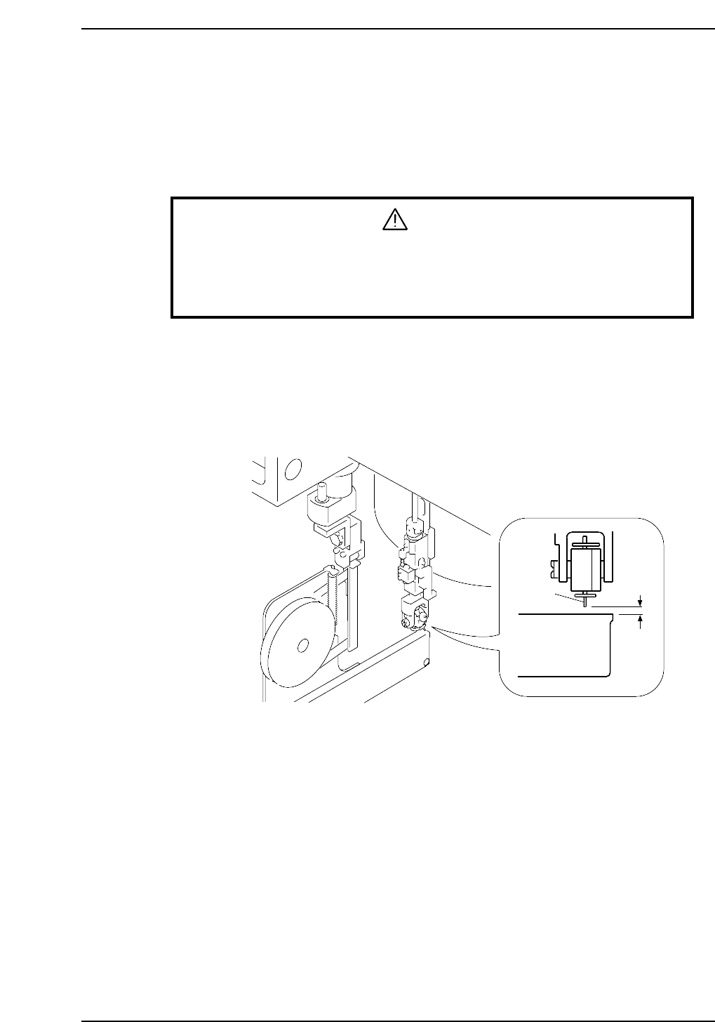
6. Use a feeder gauge to ensure a space of 0.65 mm between the tip of the nozzle and
the feeder (pick-up height).
0.65mm
Feeder
Nozzle
CP6M5027
Part 5 Chapter 3 Station Adjustments
Edition 1.0 5-3-11 CP-6-series Mechanical Reference
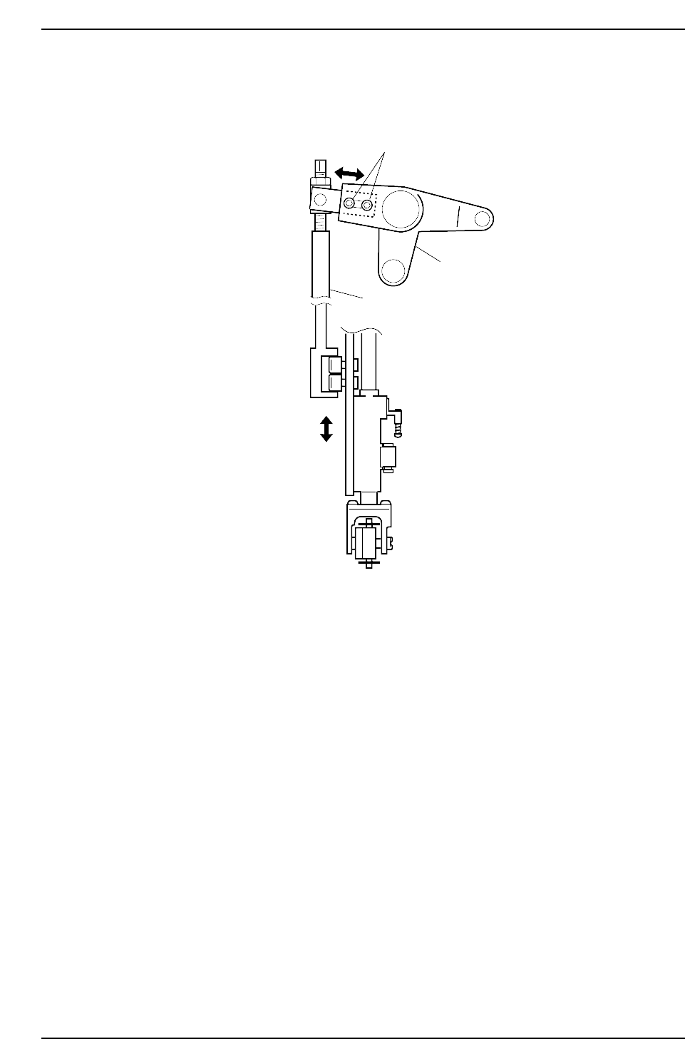
7. Adjust the sliding portion of the cam lever to obtain the pick-up height if the
measurements previously mentioned are out of the range specified on the
previous page.
8. It is necessary to check the slider adjustment once this measurement has been
carried out. Only when the values for both adjustments fall within the permissible
ranges, is the procedure complete.
Adjustment bolt
Cam lever
Vertical nozzle rod
CP6M5028
Part 5 Chapter 3 Station Adjustments
Edition 1.0 5-3-12 CP-6-series Mechanical Reference
3.1.5 Adjusting the Nozzle UP Limit Sensor
The sensor which detects the height of the nozzle UP/DOWN rod is mounted inside the
cam box. Adjust the sensor’s mounting position so that the sensor switches ON when
the nozzle is at its UP limit.
WARNING
• Turn off the 200 V servo power before carrying out this work.
• Exercise extreme caution when working on the machine if the cam is
not at its origin (0 deg.). Recoil of the cam axis can endanger the
operator.
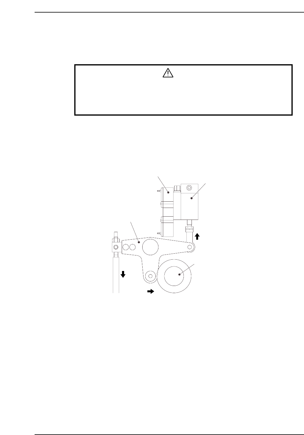
1. Set the cam axis at the 0-degree position.
2. Execute the following I/O commands to pull in the ST1 pickup stop cylinder
(located in the cam box):
[SET] - [MANUAL] - [I/O] - [Standard I/O] - [OUTPUT] -> Y020 PICKUP SOL ON
The cam lever will then follow the cam axis.
Solenoid valve
ST1 pick-up stop cylinder
Cam lever
Cam axis
Cam lever follows cam axis
CP6M5029
Part 5 Chapter 3 Station Adjustments
Edition 1.0 5-3-13 CP-6-series Mechanical Reference