CP-6-series Mechanical Reference.pdf - 第78页
Notes: Part 2 Chapter 1 Changing the Conveyor Width Edition 1.3 2-1-2 CP-6-series Mechanical Reference
1. Changing the Conveyor Width
Point
Conveyor width adjustments must be performed simultaneously for the in-conveyor,
XY-table, and the out-conveyor which are all linked.
Adjust the conveyor to a width which permits the boards to be transported and clamped
in a smooth manner.
Procedure
1. Perform the following command sequence to move the XY-table to the loading
position: [LOADER] - [LOADING PSTN] - START button.
2. Use the [LIFTER▲] command to raise the XY-table until it is linked to the in/out-
conveyor.
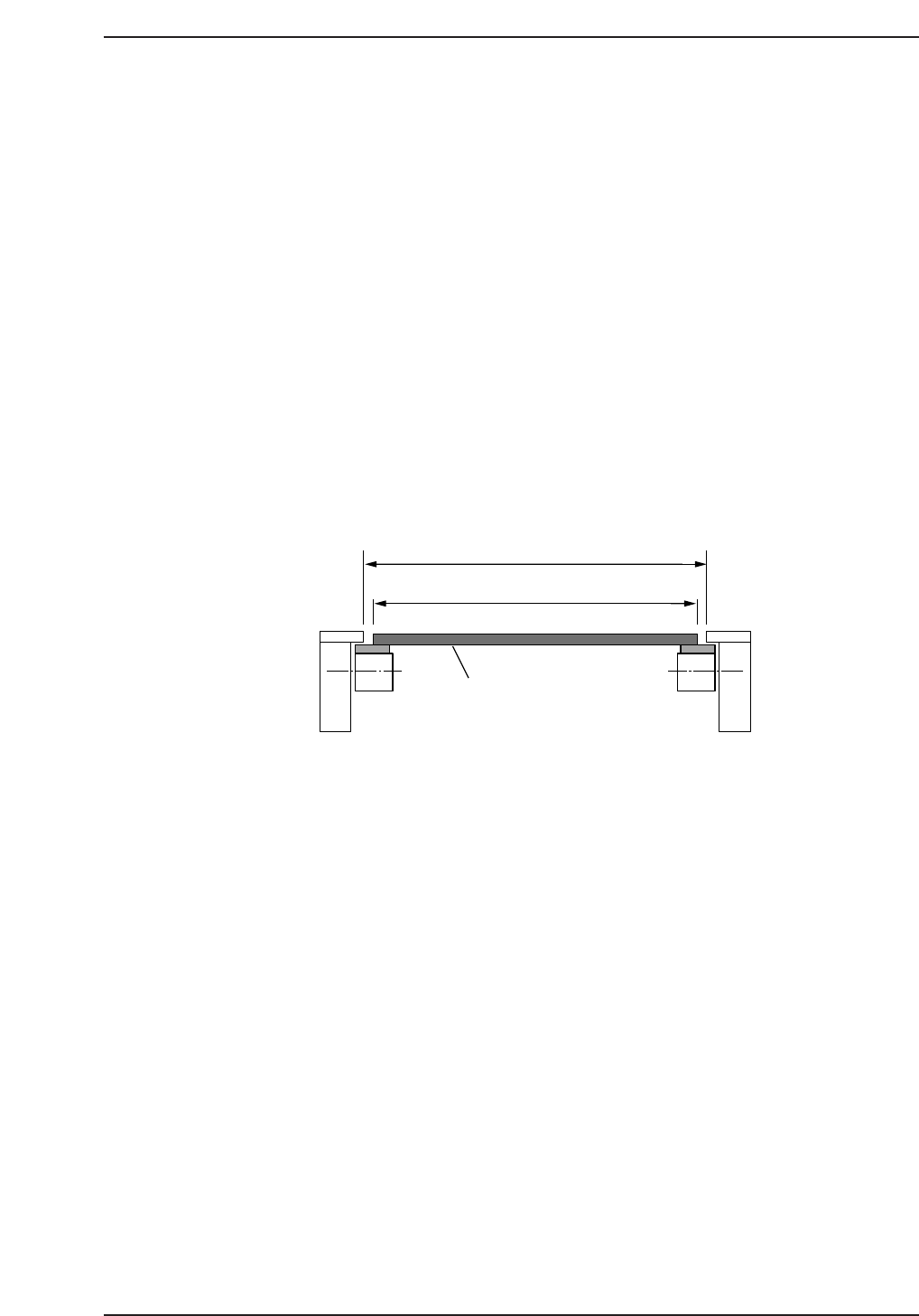
3. Turn the handle on the out-conveyor to adjust the conveyor width until the panel
can be conveyed smoothly. First increase the conveyor width then reduce it to
between 0.5~1.0 mm wider than the panel width (W) .
On CP-652C machines, be sure to adjust the conveyor above the noise-reduction
box in the same manner as that described above.
4. Use the [LIFTER▼] command to lower the XY-table.
5. Run a board through the conveyor system to verify that the board is conveyed in a
smooth manner.
Caution: Be sure to check the positions of the backup pins after adjusting the conveyor width to
be sure that they do not interfere with the conveyor rail.
On CP-643E/643ME machines, the main conveyor and out-carrier can be linked using
the following command sequence: [LOADER] - [LOADING PSTN] - [WIDTH CH ADJ].
Refer to the CP-643 System Reference Manuall for further details.
After linking the main conveyor and the out-carrier, turn the conveyor width adjusting
handle to adjust the conveyor width to the width of the board in the same manner as that
described above.
W + (0.5~1.0 mm)
W
C7SM2001Ea
Panel
Part 2 Chapter 1 Changing the Conveyor Width
Edition 1.3 2-1-1 CP-6-series Mechanical Reference

Notes:
Part 2 Chapter 1 Changing the Conveyor Width
Edition 1.3 2-1-2 CP-6-series Mechanical Reference
2. Feeder Setting
Point
The feeder must be correctly set on the device table in order for parts to be accurately
picked by the nozzles.
Procedure
WARNING
Turn off the 200 V servo power before carrying out this procedure.
Check that the feeders are correctly set on the device table or the pallet (CP-652C) as
described below.
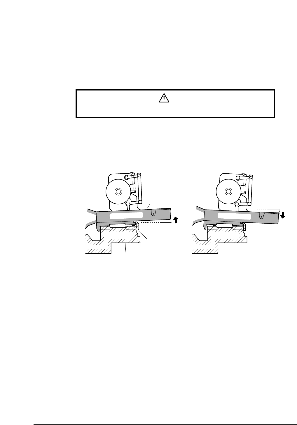
1. Ensure that no foreign matter (waste paper, dust, etc.) becomes sandwiched
between the feeders and the device table. Remove any foreign matter from the
device table and the bottom of the feeder before setting feeders.
2. Check for any tape leaf deformities.
Feeder
Foreign matter
Device table
CP6M2002
Part 2 Chapter 2 Feeder Setting
Edition 1.0 2-2-1 CP-6-series Mechanical Reference