CP-6-series Mechanical Reference.pdf - 第61页
Notes: Part 1 Chapter 2 Functions of Each Component Edition 1.1 1-2-22 CP-6-series Mechanical Reference

The second purpose of the MP board is to watch for a drop in the main AC voltage. The
100V AC secondary side of the main transformer is monitored (the three red wires
leading into the bottom of the card are for this purpose). The MP board is able to detect a
full wave failure within 16.6 ms and begin its next task.
The final job of the MP board is to supply the CPU card with enough voltage to preserve
the contents of the memory. A 3.6 VDC 2,000 MAH Lithium battery is used to do this.
When the battery is drained, the machine will lose its memory (indicated by the message
“Memory back-up NG”) when the power is turned off.
2.7 Pneumatic Control System
This controls the flow and pressure of air (and/or vacuum) from the inlet to where it is
required.
Part 1 Chapter 2 Functions of Each Component
Edition 1.1 1-2-21 CP-6-series Mechanical Reference

Notes:
Part 1 Chapter 2 Functions of Each Component
Edition 1.1 1-2-22 CP-6-series Mechanical Reference
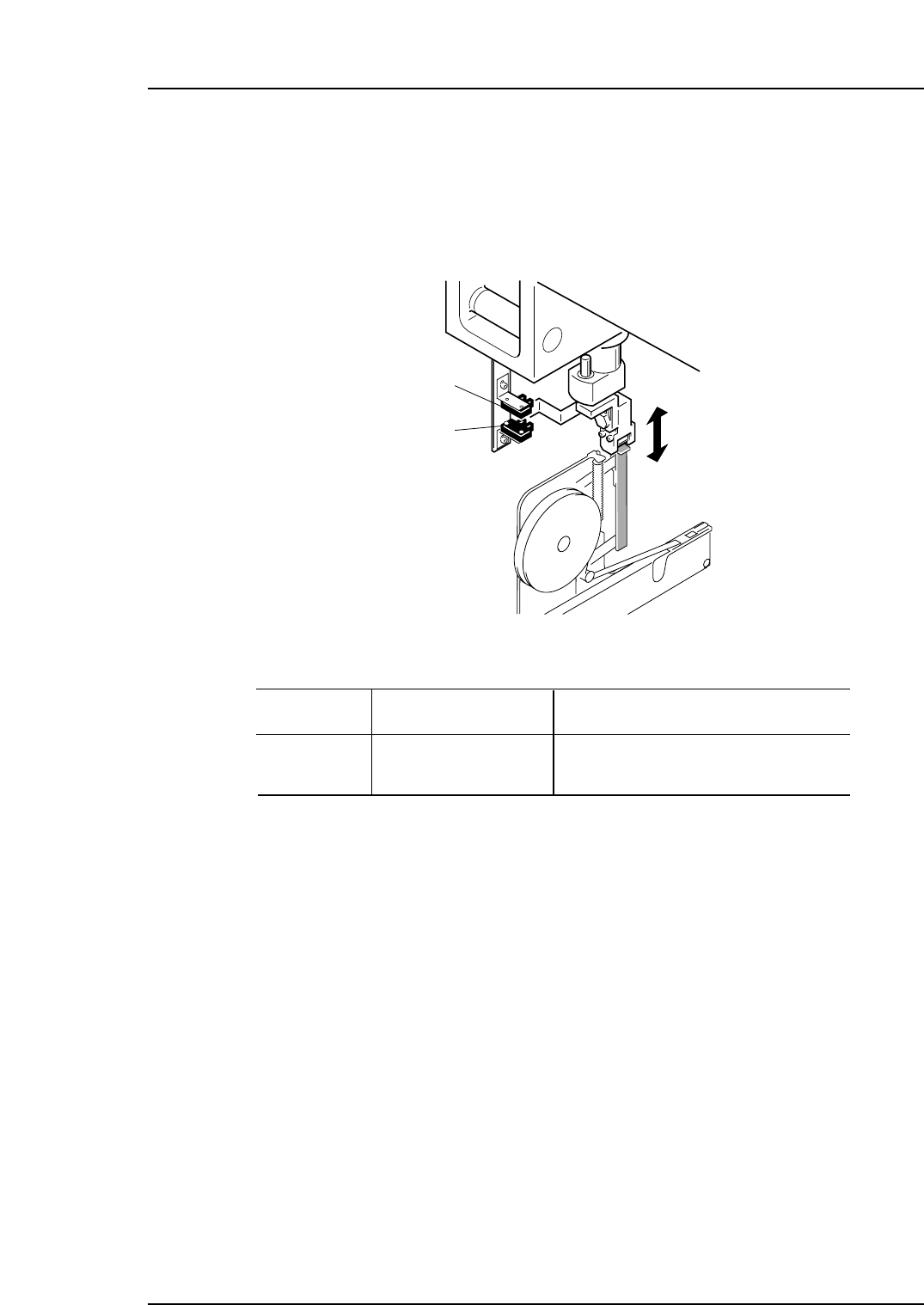
3. Sensor Positions
3.1 Stations
Station 1 (feeder lever)
I/O Address
X03C
X03D
I/O Name
Description
FEEDING FW POS
FEEDING BW POS
Station 1 feeding lever advance limit
Station 1 feeding lever retract limit
CP6M1034a
CP6M1034
X03D
X03C
Part 1 Chapter 3 Sensor Positions
Edition 1.0 1-3-1 CP-6-series Mechanical Reference