CP-6-series Mechanical Reference.pdf - 第241页
2.5 Boot-up in P AM Mode Insert the PAM software ROM card and reset start the machine. The machine will boot up in the PAM mode. Transmit the Proper data, status data and the programs once the machine reboots. Reboot the…

2.4 Simplified Measurement Technique
The CP-6 series is designed so that the nozzle shafts are aligned in a straight line relative
to the head shafts. When a nozzle is changed, there is almost no variation between the
nozzle centers. This means that a PAM measurement can be performed for only 1 of the
6 nozzles, with the results for that nozzle applying to the other nozzles. The accuracy
can therefore be checked simply by repeating the nozzle center measurement.
1. Use the standard 3216R part data as the measurement part data.
2. Assuming that the following nozzle combination is used, a 1.3 mm nozzle is
mounted at No.3.
• No.1 nozzle 0.7 mm
• No.2 nozzle 1.0 mm
• No.3 nozzle 1.3 mm
• No.4 nozzle *.* mm
• No.5 nozzle *.* mm
• No.6 nozzle *.* mm
3. Create the Nozzle Assignment Table as shown below.
• Nozzle Assignment Table
Nozzle_No Nozzle_Size Back_light_size Bend_Limit Nozzle_type
1 0.0 00 0.000 0
2 0.0 00 0.000 0
3 1.3 12 0.050 0
4 0.0 00 0.000 0
5 0.0 00 0.000 0
6 0.0 00 0.000 0
4. Copy the No.3 measurement results to all the other nozzles.
5. Perform a nozzle center measurement.
6. Run PAM again to verify that an accuracy result is obtained.
Part 7 Chapter 2 Placement Accuracy Measurement
Edition 1.0 7-2-5 CP-6-series Mechanical Reference
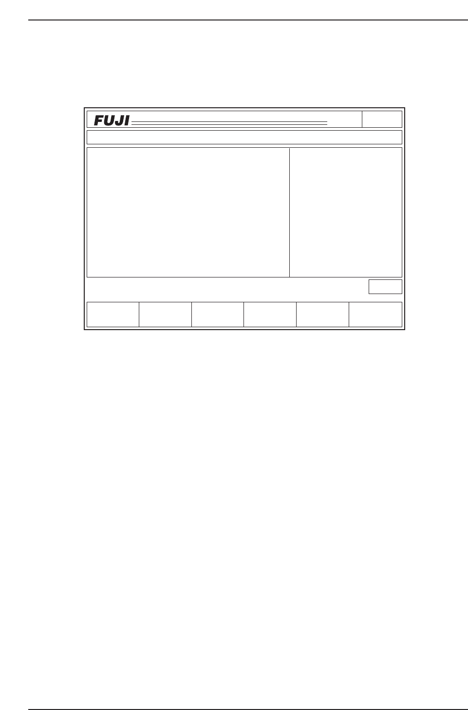
2.5 Boot-up in PAM Mode
Insert the PAM software ROM card and reset start the machine. The machine will boot
up in the PAM mode. Transmit the Proper data, status data and the programs once the
machine reboots. Reboot the machine after transmitting the data.
• The display shown above is the first screen in the PAM mode. "PAM Mode"
displays on the screen if the machine boots up in the PAM mode.
• The Proper data measurements for the machine and the Mark camera (excluding
those for station 11) must be complete prior to using the PAM software.
Page000
CP_6.PROGRAM
000000000000
000000000000
Prod 00000 Sche 00000
P1.00 off line
ST 1N
ST 2N
ST 3N
ST 6N
ST 7N
ST 8N
ST10N
ST11N
3D 5Er****
3D 5Er****
3D 5Er****
3D 5Er****
3D 5Er 0
3D 5Er 0
3D 5Er 0
3D 5Er 0
Machine Not Zero-Set
✽
Press START
jog
XY
C
PAM
LOADER PROGRAM SET
STATUS
P Mode
Recovery
T Mode
PAM Mode
Product
E Pass
Joint
CP6M7006
Part 7 Chapter 2 Placement Accuracy Measurement
Edition 1.0 7-2-6 CP-6-series Mechanical Reference

2.6 ST11 Proper Data Setting Procedure
Follow the procedures listed below to adjust the Proper data for station 11.
Procedure
1. Replace the Nozzles
Install 1.3 mm nozzles (with 12 mm reflective disks) in all the nozzle holders.
2. Mounting the Cartridge
PAM requires only 1 cartridge for a paper tape (width: 8 mm, feed pitch: 4 mm). The
PAM dummy parts reel is set on the cartridge, and the cartridge is then mounted on
device number 1.
3. Loading the PAM Measurement Board
Use the [LOADER] command to load the PAM measurement board.
Note: In the PAM mode, the [LOADER] command must always be used to load and unload the
board.
4. Nozzle Center Measurement
Perform a nozzle center measurement. The Nozzle Assignment Table should be such
that nozzles with bend amounts of 0.05 mm or more are skipped.
Replace the unacceptable nozzles, then repeat the nozzle center measurement using the
following command sequence:
[SET] → [MANUAL] → [NOZZLE] → [CENTER] → START button
Note: Refer to 2.1 “The Need for Station 11 Proper Data Calibrations” section of this chapter for
information concerning the necessity of nozzle center measurements.
Part 7 Chapter 2 Placement Accuracy Measurement
Edition 1.0 7-2-7 CP-6-series Mechanical Reference