CP-6-series Mechanical Reference.pdf - 第190页
5. Adjust the sensor ’ s mounting position by loosening the two sensor lock screws and sliding the sensor in the front/back directions. CP6M5032 Sensor Lock screws Dog Part 5 Chapter 3 Station Adjustments Edition 1.0 5-3…
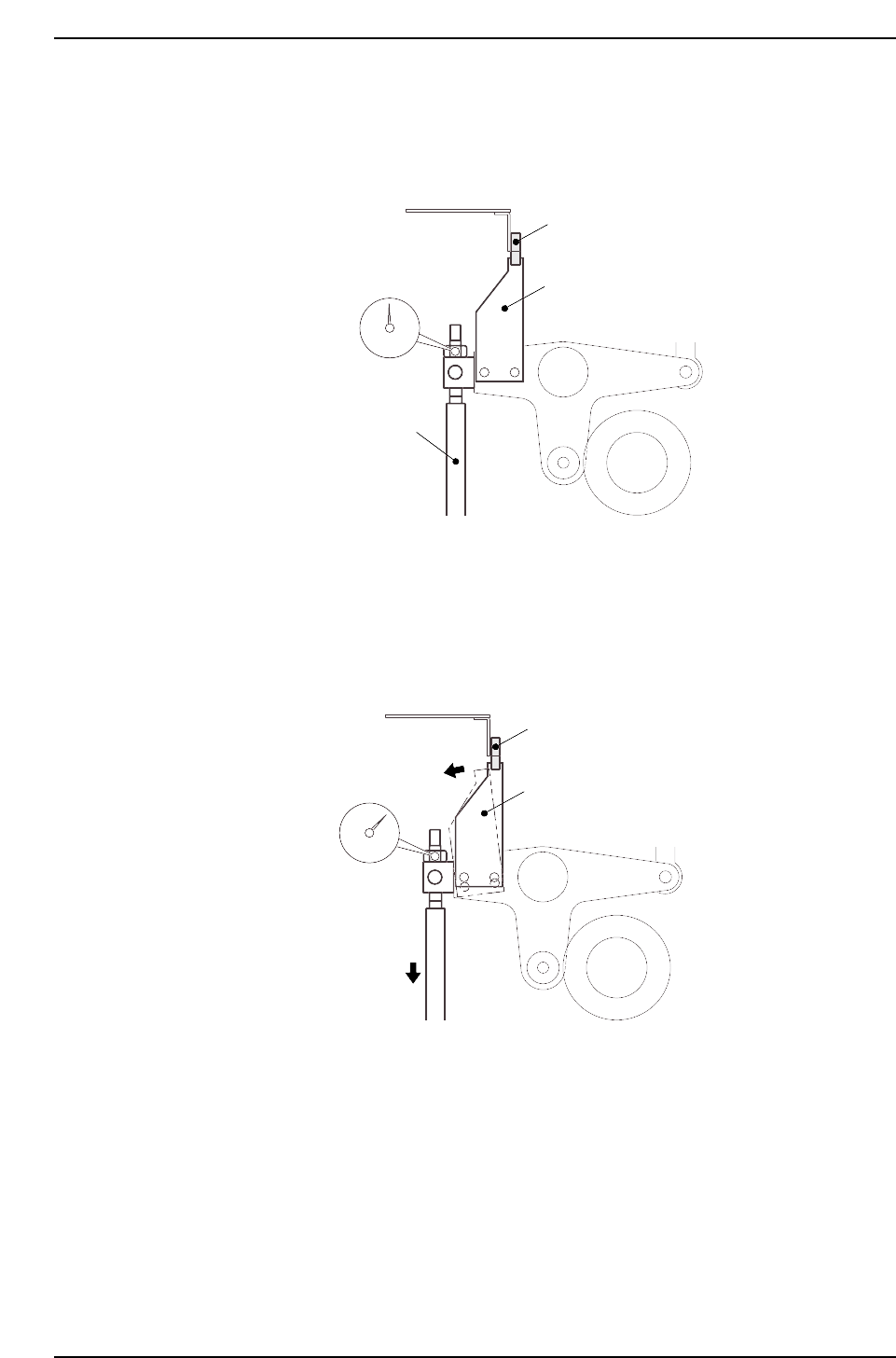
3. Place a dial gauge on the nozzle UP/DOWN rod and set the gauge reading to “0”.
In this condition, the cam axis will be at its 0-degree position, and the nozzle
UP/DOWN rod will be at its UP limit position. Verify that the nozzle UP limit
sensor is ON (I/O INPORT X06A ST1 UP POS is ON).
4. While observing the dial gauge, rotate the cam axis in the forward direction to
lower the nozzle UP/DOWN rod. Adjust the sensor’s mounting position so that
the sensor switches OFF (I/O INPORT X06A ST1 UP POS switches OFF) when the
rod has been lowered 0.3 to 0.4 mm.
CP6M5031
Nozzle UP limit sensor OFF
Dog
Rod lowered
0.3 to 0.4 mm
CP6M5030
Nozzle UP limit sensor ON
Dog
Nozzle UP/DOWN rod
Set dial gauge to “0”
Part 5 Chapter 3 Station Adjustments
Edition 1.0 5-3-14 CP-6-series Mechanical Reference
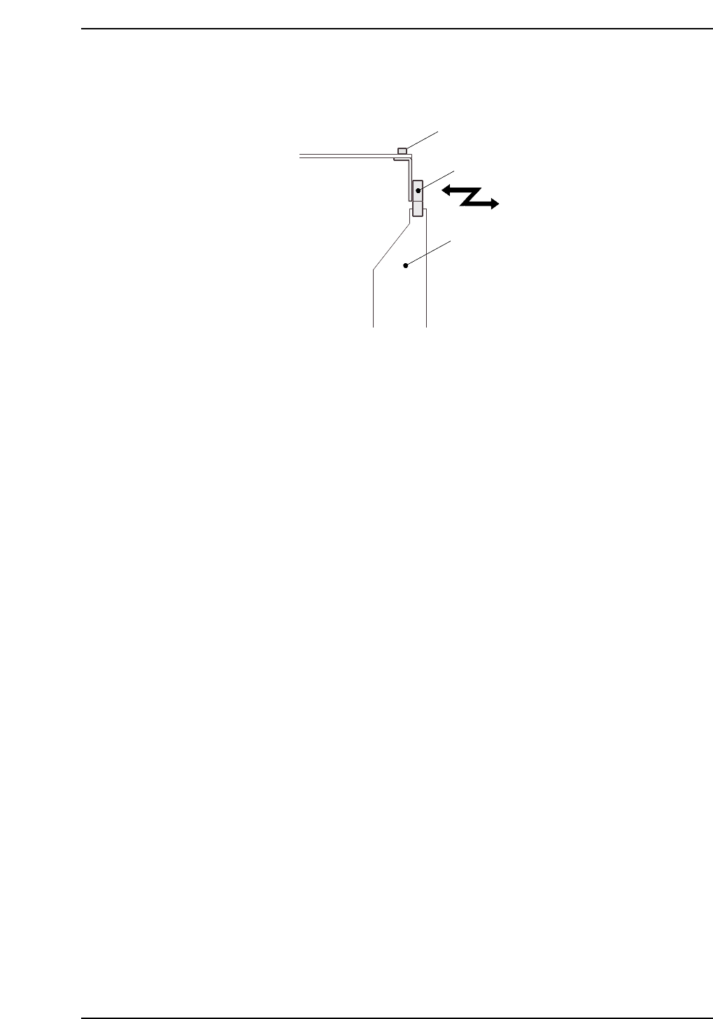
5. Adjust the sensor’s mounting position by loosening the two sensor lock screws
and sliding the sensor in the front/back directions.
CP6M5032
Sensor
Lock screws
Dog
Part 5 Chapter 3 Station Adjustments
Edition 1.0 5-3-15 CP-6-series Mechanical Reference
3.1.6 Nozzle Vacuum Valve ON
The nozzle vacuum goes from OFF to ON with the movement of the mechanical valve at
station 1. Vacuum pressure for part pick-up forms inside the nozzle when the valve is
open.
Nozzle Vacuum Valve Lever Adjustment
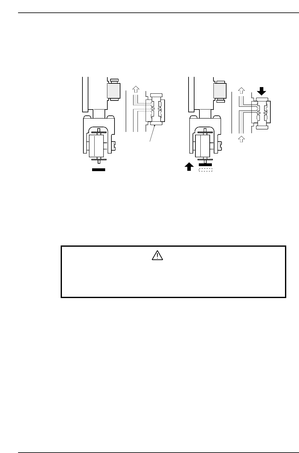
1. Adjust the valve ON/OFF operation at the reference head.
The reference head is ascertained by raising each spool as shown in the figure
above and measuring its height.
The head with the lowest spool is used as the reference (use a dial gauge).
2. Select [SET] - [MANUAL] - [I/O] and then press the EMERGENCY STOP button
to take the 200 V down to 100 V.
WARNING
• Turn off the 200 V servo power before carrying out this work.
• Exercise extreme caution when working on the machine if the cam is
not at its origin (0 deg.). Recoil of the cam axis can endanger the
operator.
3. With the first nozzle's Y020 pick up solenoid OFF, rotate the cam to an angle of
175°, and adjust the distance between the mechanical spool and the lever so that it
is 0.7 mm. Adjustment can be made at bracket "A".
Vacuum ONVacuum OFF
Air
Air
Spool
CP6M5033
Part 5 Chapter 3 Station Adjustments
Edition 1.0 5-3-16 CP-6-series Mechanical Reference