CP-6-series Mechanical Reference.pdf - 第289页
Double Board Detection (CP-643E / CP-643ME) The second board check sensor also functions to detect a double board loading condition. When boards are being fed manually, this function prevents interference between the mac…
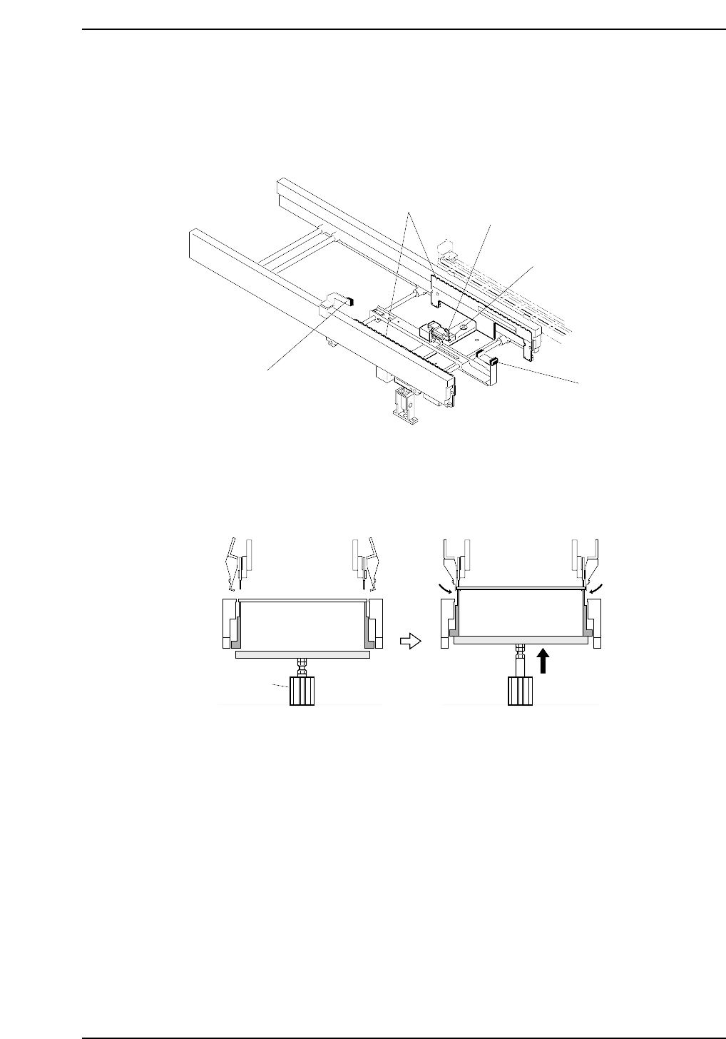
2. In-Conveyor
In addition to the guide rails, T-type conveyor belts, and motor that the standard
conveyor is equipped with, the in-conveyor in this system is also configured with a lifter
and mid-stopper.
The lifter moves up and down by means of an air cylinder thereby allowing boards on
the in-conveyor to be pushed up. Boards that have been lifted are received by the in-
carrier.
CP6M10004
Air cylinder
CP6M10003
Lifter
Mid-stopper
Second board check sensor
First board check sensor
Sensor for second board
check and double board detection
Part 9 Chapter 2 In-Conveyor
Edition 1.0 9-2-1 CP-6-series Mechanical Reference

Double Board Detection (CP-643E / CP-643ME)
The second board check sensor also functions to detect a double board loading condition.
When boards are being fed manually, this function prevents interference between the
machine and boards which may protrude from the carrier. The sensor switches on if the
board is not contained within the shaded area shown in the illustration below.
CP6M10005
2 mm Max. board
length
457 mm
Double board check sensor
Part 9 Chapter 2 In-Conveyor
Edition 1.0 9-2-2 CP-6-series Mechanical Reference
2.1 Adjustment of the Lifter Air Cylinder Sensors
WARNING
• Turn off the 200 V servo power before carrying out this work.
• The CP-643E/643ME conveyor is equipped with laser sensors.
In areas where there is a risk of eye damage from the laser beams,
be sure to install a laser beam shield at the laser emission area
before performing this sensor adjustment procedure.
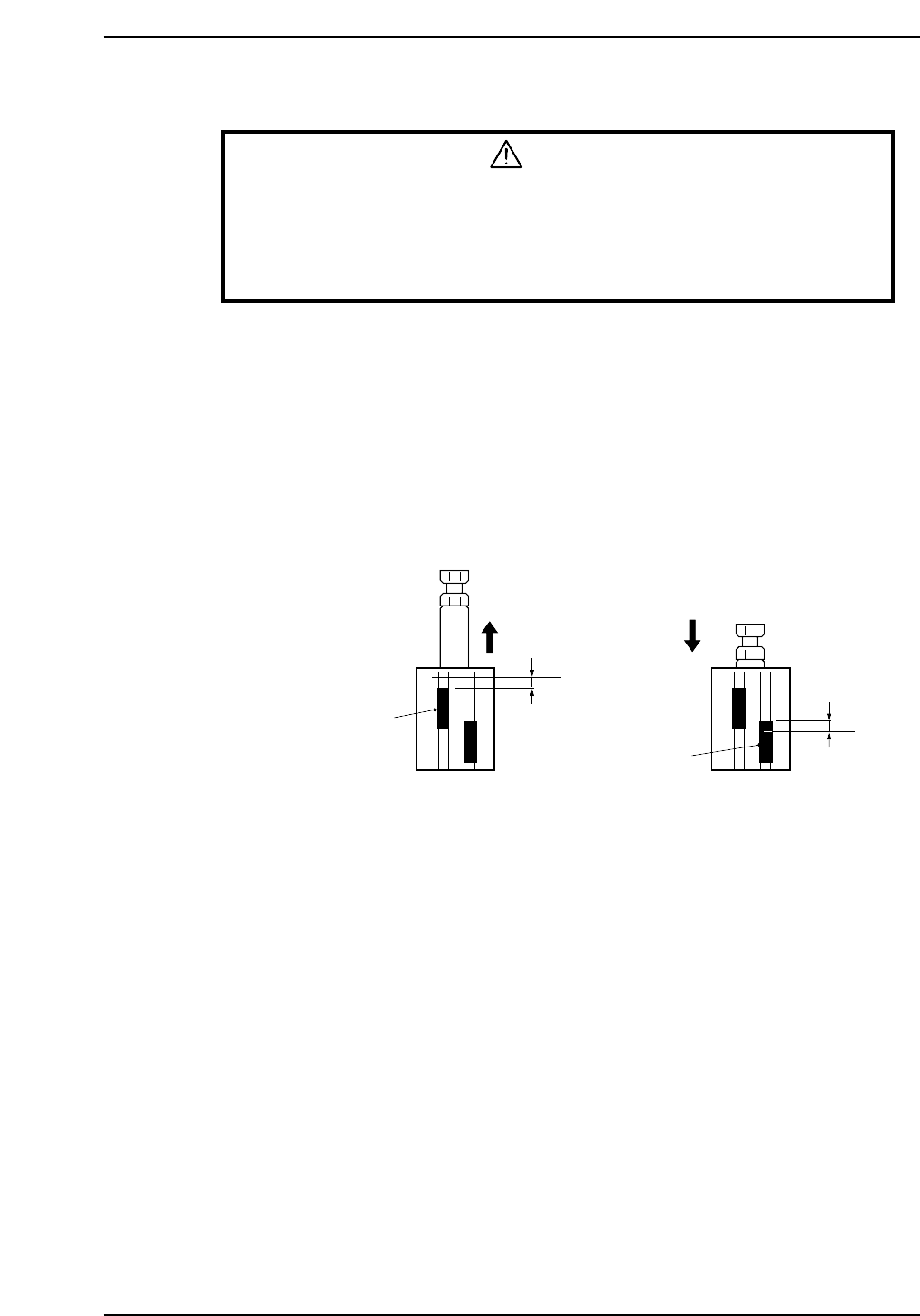
1. Release the air inside the cylinder.
2. Raise the lifter, set the cylinder in the extended status and check the position at
which the upper limit sensor comes ON.
3. From the position at which the sensor comes ON, lower the upper limit sensor by
0.5 mm and secure it in place.
4. Lower the lifter, set the cylinder in the contracted status, and check the position at
which the lower limit sensor comes ON.
5. From the position at which the sensor comes ON, raise the lower limit sensor by
0.5 mm and secure it in place.
a
b
Upper limit sensor
Lower limit sensor
0.5 mm
0.5 mm
CP6M10006
a: Position at which the upper limit sensor comes ON with the cylinder in the extended status
b: Position at which the lower limit sensor comes ON with the cylinder in the contracted status
Part 9 Chapter 2 In-Conveyor
Edition 1.0 9-2-3 CP-6-series Mechanical Reference