CP-6-series Mechanical Reference.pdf - 第238页
2.2 Notes on Using P AM In order to use PAM, the machine’s control card ROM must be replaced with the PAM card ROM. Production operations are not possible while the PAM card ROM is installed in the machine. To restore th…
2.1 The Need for Station 11 Proper Data Calibrations
Corrections in Station 11 Proper data are required to counter the mechanical deviation of
each nozzle at Station 11.
Although it is possible to measure the nozzle centers of Station 6 with the parts camera, it
is impossible to measure the centers at Station 11. The placement position of parts will
be inaccurate without compensating for these mechanical deviations because, it is
impossible for each nozzle to stop at the exact same point.
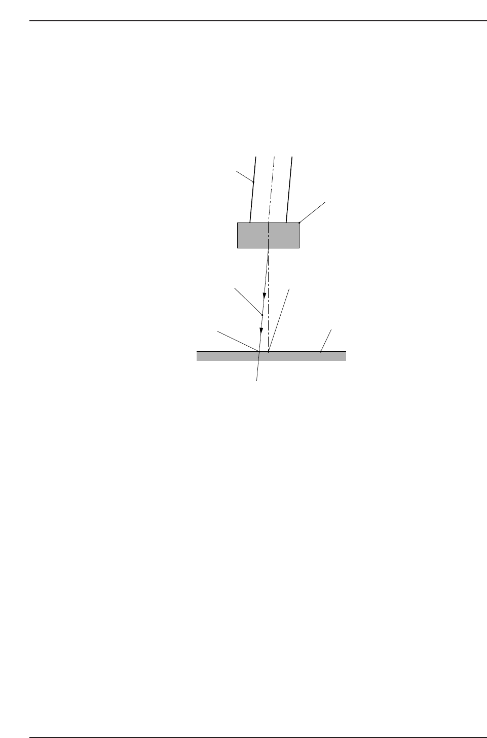
As shown in this illustration, when a nozzle cannot move in a completely vertical
direction due to mechanical errors, the center of a part, as seen by the vision processing
system, and the actual center may not correlate.
The measurement performed by PAM involves a process in which dummy chips are
actually placed on a mark reference board, with the chip placement accuracy being
checked by a mark camera. Each nozzle is rotated to 0 degrees, 90 degrees, 180 degrees
and 270 degrees and the vision processing data for the placed parts then undergoes
statistical processing to provide an accurate measurement of the mechanical error
amount.
Nozzle
Decending
trajectory
Board
Part center detected
by Vision Processing
Part center
at placement
Part
CP6M7005
Part 7 Chapter 2 Placement Accuracy Measurement
Edition 1.0 7-2-2 CP-6-series Mechanical Reference

2.2 Notes on Using PAM
In order to use PAM, the machine’s control card ROM must be replaced with the PAM
card ROM. Production operations are not possible while the PAM card ROM is installed
in the machine. To restore the machine’s production capabilities, the machine’s control
card ROM must be re-installed.
Moreover, the CP-6 PAM does not support the following commands and functions.
Commands
• Block skip
• Recovery
• Pass Mode
• Turnover Operation
• Nozzle skip
Functions
• Nozzle skip following a nozzle-centering alarm
• Statistical nozzle skip
• HELPS
Part 7 Chapter 2 Placement Accuracy Measurement
Edition 1.0 7-2-3 CP-6-series Mechanical Reference

2.3 Procedure Overview
Part Data and Nozzle Assignment Table
Prepare the part data and Nozzle Assignment Table for PAM.
1. 6 types of part data must be created.
The 6 types of part data are based on the standard 3216R part data, with only the
nozzle size being specified (input item: Nozzle_size_CP6).
• Part Data
Nozzle
No.1_3216 1.1 mm Data for part pick-up with the No.1 nozzle
No.2_3216 1.2 mm Data for part pick-up with the No.2 nozzle
No.3_3216 1.3 mm Data for part pick-up with the No.3 nozzle
No.4_3216 1.4 mm Data for part pick-up with the No.4 nozzle
No.5_3216 1.5 mm Data for part pick-up with the No.5 nozzle
No.6_3216 1.6 mm Data for part pick-up with the No.6 nozzle
2. Create the Nozzle Assignment Table as shown below.
• Nozzle Assignment Table
Nozzle_No Nozzle_Size Back_light_sizeBend_Limit Nozzle_type
1 1.1 12 0.050 0
2 1.2 12 0.050 0
3 1.3 12 0.050 0
4 1.4 12 0.050 0
5 1.5 12 0.050 0
6 1.6 12 0.050 0
Notes: Regarding the input items at the part data and Nozzle Assignment Table
1. Although the 1.3 mm size nozzle is used for all the PAM nozzles (Nos.1 to 6),
different sizes (in 0.1 mm increments) must be entered as shown above in the “Part
Data” and “Nozzle Assignment Table” in order to differentiate between the 6 nozzles
(this prevents nozzle changes during PAM placement operations). By entering the
nozzle sizes in 0.1 mm increments, parts will only be picked up by the nozzle number
specified in the program.
Within the vision processing system for PAM, however, all the nozzle sizes are
processed as 1.3 mm.
2. If there are not enough 1.3 mm nozzles, perform measurement by placing all 20 1.3
mm nozzles on each head in order from No.1 to No.6 nozzle positions.
PAM Measurement
The PAM measurement occurs using the 20 No.1 nozzles at the 20 heads. If an accuracy
measurement fails, it is repeated until a result is obtained.
Note: The No.2 to No.6 nozzles are not used in the accuracy measurement.
No.2 to No.6 Nozzle Measurement
The No. 2 to No. 6 nozzle measurements are performed in the same manner as step 2.
Part 7 Chapter 2 Placement Accuracy Measurement
Edition 1.0 7-2-4 CP-6-series Mechanical Reference