CP-6-series Mechanical Reference.pdf - 第146页
Part 4 Setup
Part 3 Chapter 3 Replacing Consumable Parts
Edition 1.6 3-3-14 CP-6-series Mechanical Reference
3.9 Replacing the Mark Camera Lamp
Procedure
Warning
Turn off the 200 V servo power before carrying out this work.
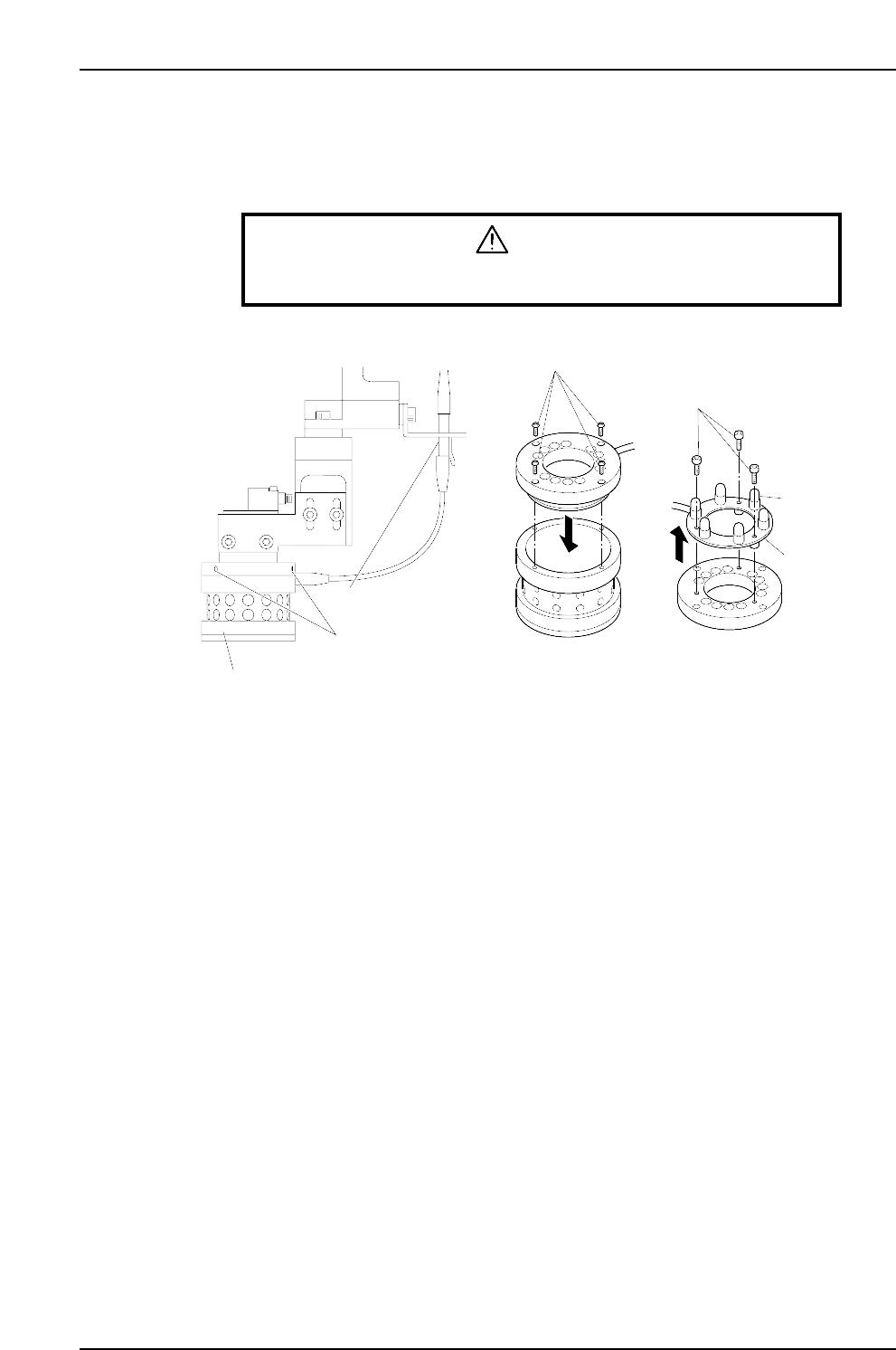
1. Unplug the lamp unit's wiring connector.
2. Loosen the 3 screws which secure the lamp unit to the CCD camera to the point
where they protrude 1 to 2 mm from the lamp unit. Lower the lamp unit and
remove it.
Note: Use care to avoid dropping the lamp unit.
3. Remove the 4 screws which secure the top part of the lamp unit, then remove the
top part of the lamp unit.
4. After removing the top part of the lamp unit, turn it upside down and remove the
3 screws which secure the light bulb PCB, then remove the PCB together with its
wiring.
5. Unplug the failed light bulb and replace it with a new one.
Note: Avoid touching the lamp glass with your hands. Fingerprints, etc., on the lamp glass
can shorten its life.
6. Reassemble the lamp unit by reversing the above procedure, then mount the lamp
unit on the CCD camera, and plug in the wiring connector.
Note: With the 200V power on, press the [F] key and the [4] inching key simultaneously to
test the lamp operation (light bulbs switch on). Press these two keys again to turn
the lamp off.
CP6M3065E
Screws
Bolts
PCB
Light bulb
Wiring connector
Lamp unit mounting screws
Lamp unit

Part 4
Setup
1. Installation
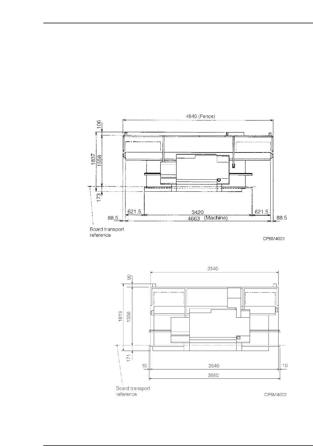
Point
Install the machine in an area spacious enough that the machine doors may be opened
and that maintenance can be performed. The following figures show the amount of
space that the machine occupies.
<CP-6>
<CP-6M>
Part 4 Chapter 1 Installation
Edition 1.0 4-1-1 CP-6-series Mechanical Reference