CP-6-series Mechanical Reference.pdf - 第218页
<When using sensors manufactured by Y AMA T AKE> Set the L-ON/D-ON switch to "D-ON" for the Station 12 CLUTCH ORIGIN amplifer and the Station 15 CLUTCH ORIGIN amplifier. Set this switch to "L-ON"…
3.9.3 Sensor Sensitivity Adjustment
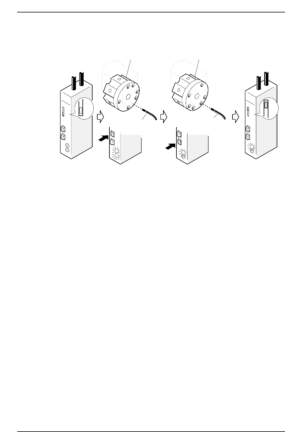
<When using sensors manufactured by SUNX>
1. Move the amplifier’s mode changing switch to the SET position.
2. Rotate the rotary holder until the sensor goes on (to a place other than a hole).
3. Press the ON button, both the red and green LEDs will then flash two or three
times and then go constant.
4. Rotate the rotary holder to an OFF position (to a hole).
5. Press the OFF button, the green LED will then flash two or three times and then go
constant.
6. Set the mode changing switch to RUN, the green LED will then start to flash. It is
possible to check the sensitivity condition by counting the number of time the LED
flashes.
No. of flashes: 0 ~ 4 5
Sensitivity: Bad Good
The setting is complete if the LED flashes five times.
7. Perform the following settings once again if the number of LED flashes is less than
five.
• Check connection between the amplifier and the fiber-optic cable.
• Confirm that the frequencies of each sensor are set so no light beam interference
occurs.
SET
ON
OFF
ON
OFF
ON
OFF
RUN
ON
OFF
RUN
SET
Rotary holder
Sensor 3
Rotary holder
Sensor 3
CP6M5066
Part 5 Chapter 3 Station Adjustments
Edition 1.0 5-3-42 CP-6-series Mechanical Reference
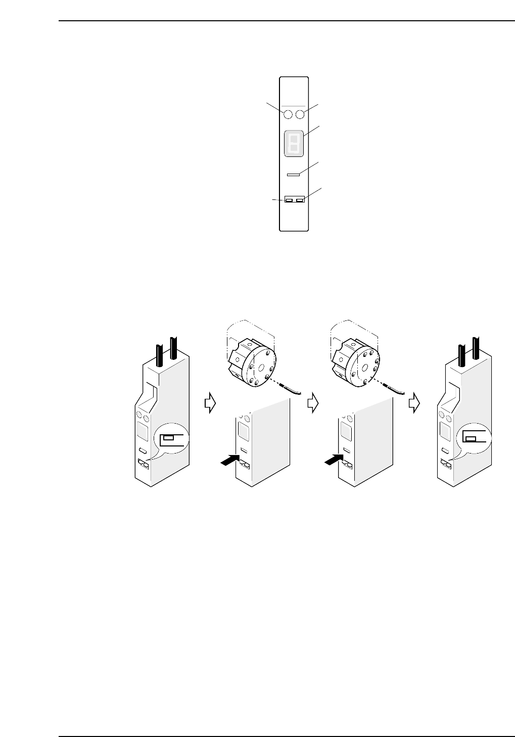
<When using sensors manufactured by YAMATAKE>
Set the L-ON/D-ON switch to "D-ON" for the Station 12 CLUTCH ORIGIN amplifer and
the Station 15 CLUTCH ORIGIN amplifier. Set this switch to "L-ON" for other
amplifiers.
1. Move the amplifier's mode change switch to the "SET" position.
2. Rotate the nozzle holder until the sensor light beam is adjacent to a solid area.
3. Rotate the nozzle holder until the sensor light beam is adjacent to a through hole.
4. Return the amplifier's mode changing switch to the "RUN" position.
At this time the sensitivity of the sensor can be checked on the digital display.
Digital display :
0 ~ 3: Stable interruption range
6 ~ 9: Stable light input range
If the display is within the stable range, setting is complete.
5. If the display is not within the stable range, check the items below and make the
necessary adjustments.
• Check the connections between the amplifier and the fiber optic cable.
• Check the position of the sensor.
SET
RUN
CP6M5068
SO
DELAY
TUNING
SET D-ON
RUN L-ON
HPY-T1
Green LED
Red LED
Digital display
Tuner
L-ON/D-ON switch
Mode changing
switch
CP6M5067
Part 5 Chapter 3 Station Adjustments
Edition 1.0 5-3-43 CP-6-series Mechanical Reference
3.10 Station 18
Nozzle Change Function
Station 18 changes the No.1~6 nozzles according to the part data and the nozzle check
data received at station 17.
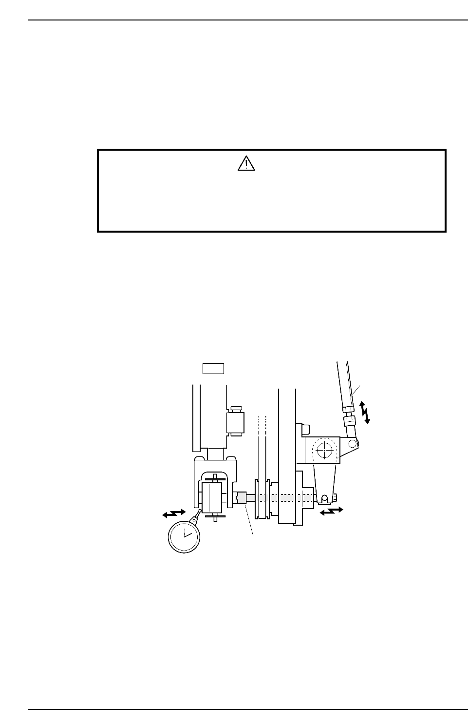
3.10.1 Meshing Point Confirmation
WARNING
• Turn off the 200 V servo power before carrying out this work.
• Exercise extreme caution when working on the machine if the cam is
not at its origin (0 deg.). Recoil of the cam axis can endanger the
operator.
Initially position the cam at an angle of 0° and turn the station 18 solenoid to ON (Y02A
NOZ SOL ON) to activate the cam lever.
<4000 Type>
1. Use the cam handle to rotate the cam to 128°.
2. Adjust the clutch to mesh with and push the nozzle holder 0.01 ~ 0.05 mm when
the cam angle is at 128°.
3. Rotate the adjustment rod if the pushing force is inadequate.
<5000 Type>
1. Rotate the cam using the cam handle to an angle of 133°.
2. When the cam is at an angle of 133°, visually confirm that the rotary clutch has
started to engage the nozzle holder.
Adjustment rod
Clutch
18st
0.01 ~ 0.05 mm
CP6M5069
Part 5 Chapter 3 Station Adjustments
Edition 1.0 5-3-44 CP-6-series Mechanical Reference