CP-6-series Mechanical Reference.pdf - 第223页
4.2 Adjusting the Sensitivity of the Sensors <X No. 422 Model used until now> 1. Set the sensor amp ALM switch to OUT, TIME to 0.04 seconds, and MODE to 1. 2. Move the XY-table to the loading position and adjust th…
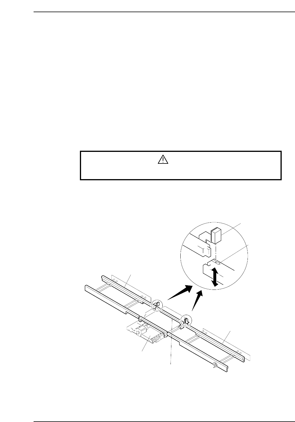
4. XY-Table Movable Rail Engagement Check
Sensor
When the XY-table is to be raised, it is necessary for the movable rails on the in-conveyor,
XY-table, and out-conveyor to all be positioned in a line.
This sensor checks whether the positions of the movable rails on the XY-table and the
conveyors are aligned so that they can be engaged without causing interference with one
another.
4.1 Sensor Position Adjustment
1. Move the XY-table to the loading position using the command operation.
[LOADER] - [LOAD PSTN] - START button
2. Press the EMERGENCY STOP button. This will cut the 200V power and leave the
machine with only the 100V power on.
WARNING
Turn off the 200 V servo power before carrying out this work.
3. Secure the sensors in place where the silver portion of the rails can be checked and
the movable rail of the XY-table can be engaged with the rails on the in- and out-
conveyors. (2 locations; on the in-conveyor side and the out-conveyor side)
In-conveyor
XY-table
Out-conveyor
Engage check
sensor
XY-table movable rail
CP6M5071
Silver portion
Part 5 Chapter 4 Engagement Rail Adjustments
Edition 1.0 5-4-1 CP-6-series Mechanical Reference
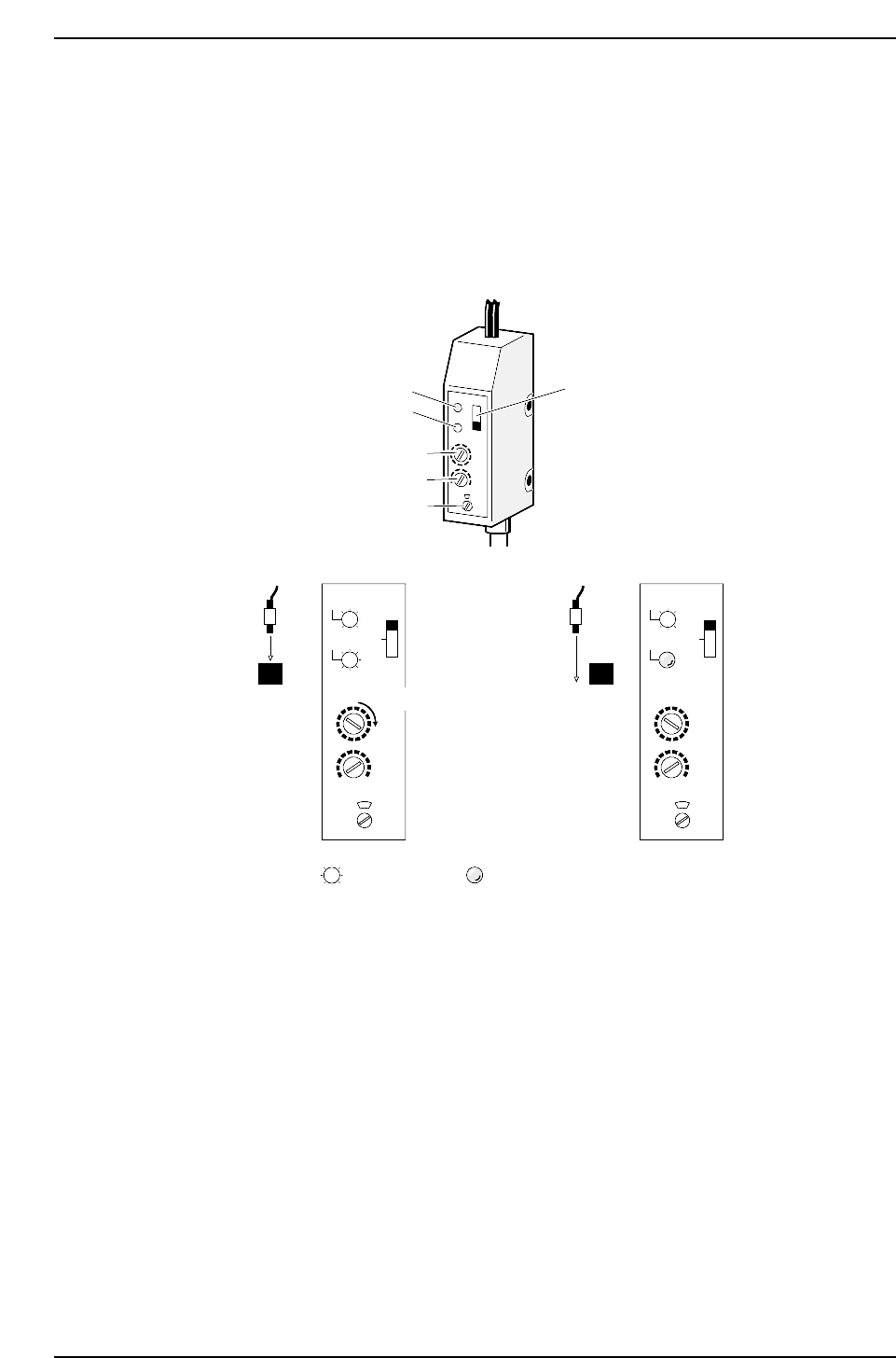
4.2 Adjusting the Sensitivity of the Sensors
<X No. 422 Model used until now>
1. Set the sensor amp ALM switch to OUT, TIME to 0.04 seconds, and MODE to 1.
2. Move the XY-table to the loading position and adjust the sensitivity using volume
1 so that both the red and green LED light up (ON) at the Z0 position and only the
red LED light goes out (OFF) moving away from this position.
Red LED
ALM switch
Green LED
Volume 1
Volume 2
Volume 3
(SEC.)TIME
MODE
SENS.
5
1
0.04
OFF
OUT
STB
STB
(1) (2)
CP6M5072
OUT
ALM
(SEC.)TIME
MODE
SENS.
5
1
0.04
OFF
OUT
STB
STB
OUT
ALM
Lit Not lit
Greater sensitivity
Part 5 Chapter 4 Engagement Rail Adjustments
Edition 1.0 5-4-2 CP-6-series Mechanical Reference
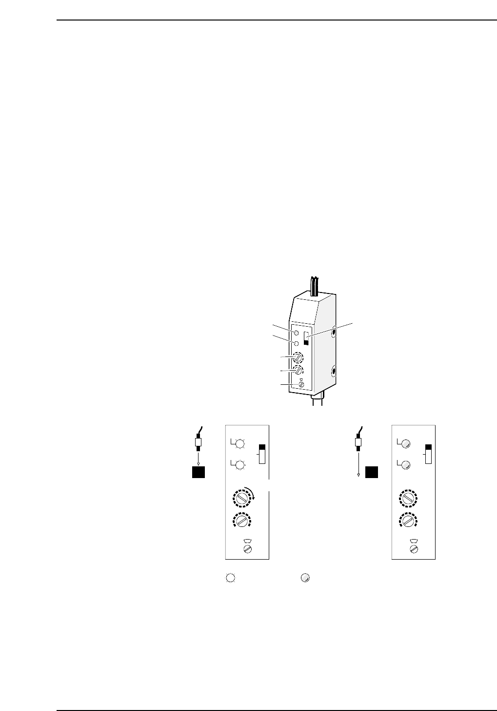
<X No. 423 model used hereafter>
1. Set the sensor amp ALM switch to OFF, TIME to 0.04 seconds, and MODE to 1.
2. Move the XY-table to the loading position and adjust the sensitivity using volume
1 so that both the red and green LED light up (ON) at the Z0 position and both
LEDs go out (OFF) moving away from this position.
(1) Move the XY-table to the loading position and set the Z0 position.
(2) Rotate the volume 1 dial so that both the red and green LED light up when
the sensor is at the engage position (silver portion). Turn the dial about two
positions in the clockwise direction from the position where the light comes
on.
3. Check the sensor operation at the next point.
• When the sensor is at the engage position (silver portion), confirm that both
the red and green LED light up when the XY-table height is between the Z0
position and the position where the upper limit sensor comes on.
• When the sensor is not at the engage position (when it is at the black
portion), verify that both the red and green LED go off with the table height
between the Z0 position and the position at which the upper limit sensor
comes on.
Red LED
ALM switch
Green LED
Volume 1
Volume 2
Volume 3
(SEC.)TIME
MODE
SENS.
5
1
0.04
OFF
OUT
STB
STB
(1) (2)
CP6M5073
OUT
ALM
(SEC.)TIME
MODE
SENS.
5
1
0.04
OFF
OUT
STB
STB
OUT
ALM
Lit Not lit
Greater sensitivity
Part 5 Chapter 4 Engagement Rail Adjustments
Edition 1.0 5-4-3 CP-6-series Mechanical Reference