CP-6-series Mechanical Reference.pdf - 第265页
1. Perform inching to raise the lifter. 2. Stop operation before the lifter reaches its highest position. 3. While monitoring the position of the cam follower moving within the groove on the ball screw, raise the lifter …
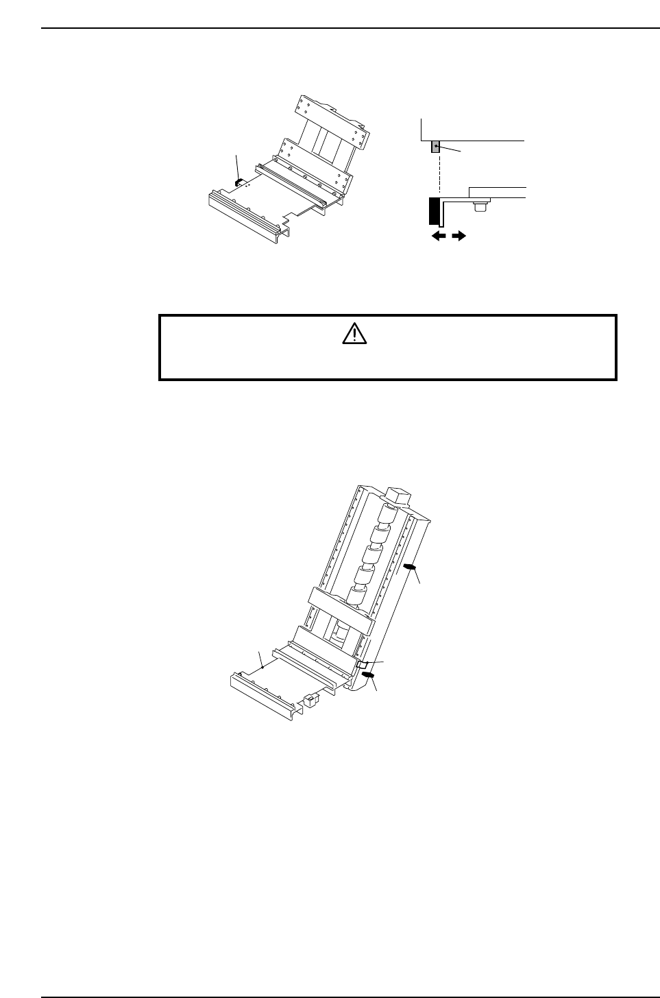
Adjust the "down" lifter in the same way.
4.2 Adjustment of the Deceleration Sensors
Warning
Turn off the 200 V servo power before carrying out this work.
There are upper and lower deceleration sensors.
These sensors are also installed on the IN-side and OUT-side elevators as well, and
should be adjusted in the same way.
Upper deceleration sensor
Lower deceleration sensor
Dog
Lifter
CP6M9022
Pallet confirmation sensor
Pallet
Dog
CP6M9021
Part 8 Chapter 4 Elevators
Edition 1.0 8-4-2 CP-6-series Mechanical Reference
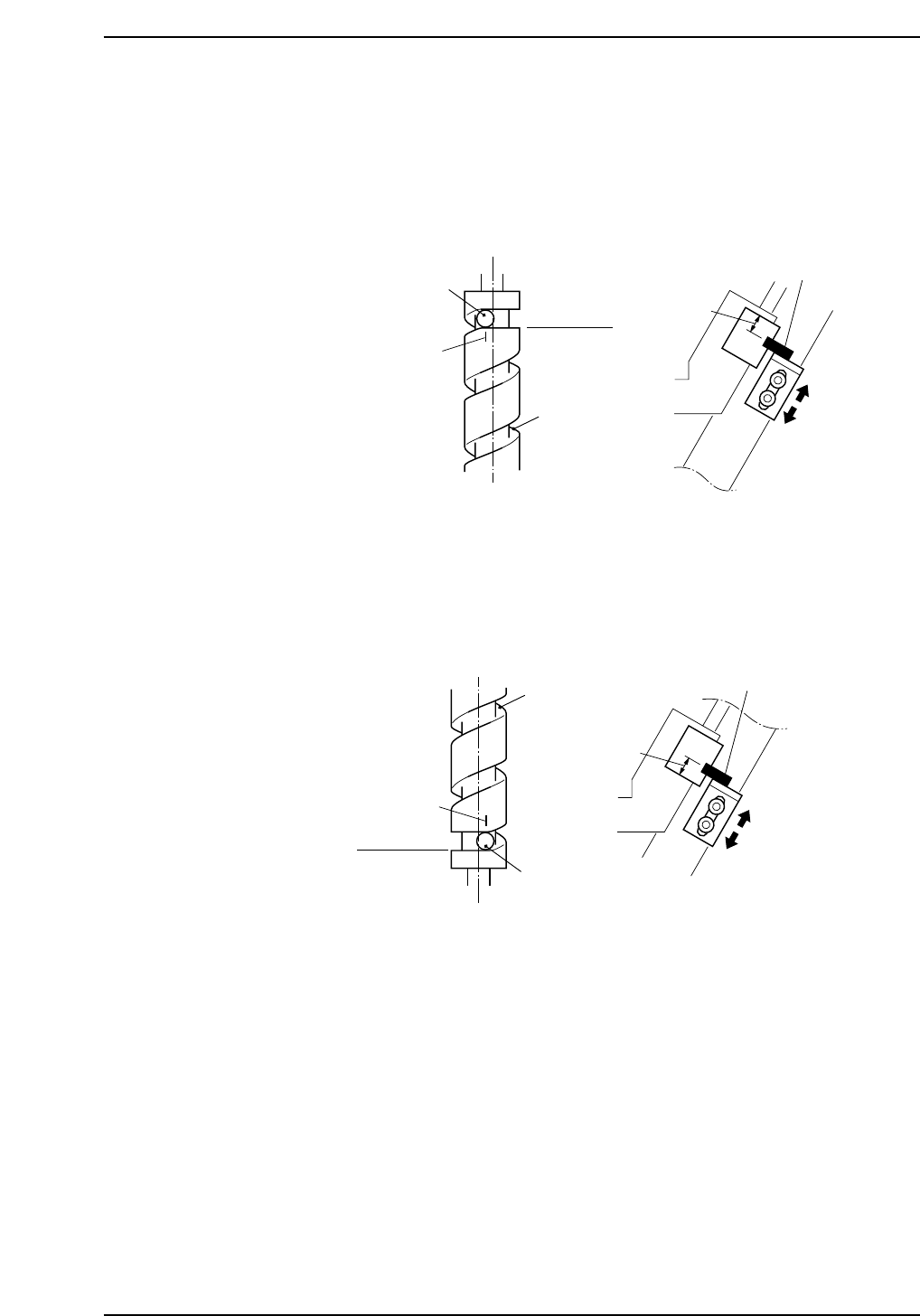
1. Perform inching to raise the lifter.
2. Stop operation before the lifter reaches its highest position.
3. While monitoring the position of the cam follower moving within the groove on
the ball screw, raise the lifter further.
4. Stop the lifter when the cam follower reaches the horizontal (flat) surface of the
cam groove.
5. At this point, adjust the position of the upper deceleration sensor so that the
distance from the center of the sensor to the upper edge of the dog is 17.0 mm.
6. Next, lower the lifter to its lowest position and adjust the lower deceleration
sensor using the same procedure as for the upper deceleration sensor.
17.0 mm
Ball screw
Cam follower
Position where stopped
Flat surface
Cam groove
Lower deceleration sensor
CP6M9024
17.0 mm
Ball screw
Cam follower
Position where stopped
Flat surface
Cam groove
Upper deceleration sensor
CP6M9023
Part 8 Chapter 4 Elevators
Edition 1.0 8-4-3 CP-6-series Mechanical Reference
4.3 Adjustment of the Stop Sensor
Warning
Turn off the 200 V servo power before carrying out this work.
There are rising and lowering stop sensors.
These sensors are installed on the IN-side and OUT-side elevators, and should be
adjusted in the same way.
Before attempting adjustment, remove the covers in the area of the sensors as well as the
stop sensors themselves.
Adjust the lowering stop sensor first.
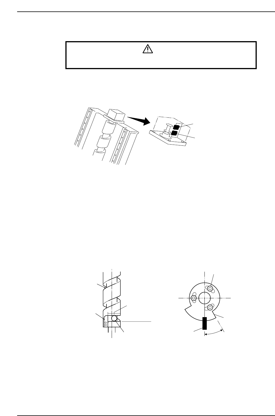
1. Perform inching to lower the lifter.
2. Stop operation before the lifter reaches its lowest position.
3. While monitoring the position of the cam follower moving within the groove on
the ball screw, lower the lifter further.
4. The cam follower reaches the horizontal (flat) surface of the cam groove.
Stop the lifter at a point intermediate between this position and the stopper.
The flat surface described here refers to the surface that is perpendicular to the ball
screw.
30°
CP6M9026
Worm camshaft
Cam groove
Stopper
Position
where stopped
Flat surface
Cam follower
Bolt
Dog
Lowering stop
sensor
Lowering stop sensor
Rising stop sensor
CP6M9025
Part 8 Chapter 4 Elevators
Edition 1.0 8-4-4 CP-6-series Mechanical Reference