CP-6-series Mechanical Reference.pdf - 第315页
1.3 Installation Procedure The installation positions for the vibration reducing units are shown below. 1. Place adhesive pads at the top and bottom faces of each unit. 2. Install each unit at its prescribed position. No…
Piping Joint List (Parts provided by manufacturer)
1.2 Purpose & Operating Principle of Unit
Purpose
The purpose of the vibration reduction unit is to minimize machine vibration from being
transmitted to the floor. The spring and air cylinder format used by this unit offers a
significant reduction in floor vibration as compared to previous systems.
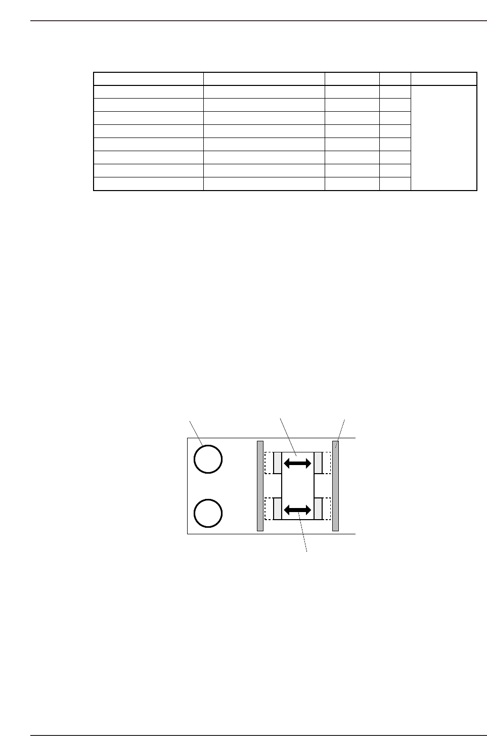
Operating Principle
Main vibration reduction unit
Each of the main units are equipped with 4 internal springs used to support the
machine’s right and left ends. Internal air cylinders extend and rub against plates to
dampen machine vibration.
Spring Unit (W2Q-434S)
Spring units utilize the spring force to support the machine.
Pneumatic Spring
The pneumatic spring uses a leveling valve to maintain a constant machine height.
Spring
Air cylinder
Plate
Extension
CP6M11002
Location Part Name Model Qty Manufacturer
Damper inlet Elbow union KQL06-00 1x2
Pneumatic spring Elbowunion KQL06-01S 1
Damper inlet T-union KQT06-00 1x2
Damper T-union KQY06-01S 1x2 SMC
Damper inlet Long elbow KQW06-99 4x2
Damper inlet, manifold Half union KQH06-01S 6x2
Piping Soft nylon (ø4) TS0604B-20 3 m
Piping Soft nylon (ø6) TS0425B-20 3 m
Part 10 Chapter 1 Vibration Reduction Unit
Edition 1.0 10-1-2 CP-6-series Mechanical Reference
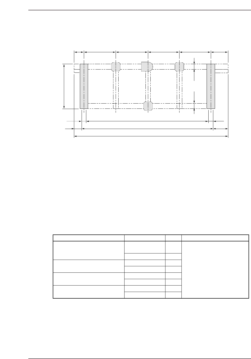
1.3 Installation Procedure
The installation positions for the vibration reducing units are shown below.
1. Place adhesive pads at the top and bottom faces of each unit.
2. Install each unit at its prescribed position.
Note: Never inflate the pneumatic spring prior to installation under the machine. Inflating
the unit prior to installation can cause it to burst.
Adhesive Pads
The adhesive pads are used to prevent positional shifts between the vibration reduction
units, the floor and the machine. Although standard adhesive pads are 4 mm thick, pads
with a 2 mm thickness are also available for height adjustment purposes. When
necessary, use a combination of both styles of pads.
Adhesive Pad List
Location Size (units: m/m) Qty Remarks
Main vibration reduction unit
(bottom)
200 x 450 x t4 4
(200x 450 x t2) 4 Sizes shown in parentheses are
Main vibration reduction unit (top) 130x 450 x t4 4 height adjusting pads
(130 x 450 x t2) 4
Spring unit (W2Q-434S) GERB x t4 3
(top & bottom) (GERB x t2) 3
Pneumatic spring (top & bottom) 380x 380 x t4 2
(380 x 380 x t2) 1
417.5750745
2930
3180 355215
125
(125) (125)
125
3750
770790277.5
1055
CP6M11003
Machine top
Part 10 Chapter 1 Vibration Reduction Unit
Edition 1.0 10-1-3 CP-6-series Mechanical Reference
Leveling (Left-Right)
Left-right tilt is controlled by the main vibration reduction unit.
Although the machine’s left-right height is normally adjusted using adhesive pads,
special adjusting plates are required when the adjustment amount exceeds 5 mm.
These adjusting plates are available in 5, 10, 15 and 20 mm thicknesses.
Leveling (Front-Back)
Front-back tilt is automatically adjusted by the pneumatic spring. A leveling valve is
activated to maintain the setting height when the back of the machine drops below the
preset height.
Adjusting Plate List
Dwg. No. Part Name Qty Thickness
9851DWAB1000 Plate 2 5 mmthick
9851DWAB1010 Plate 2 10mmthick
9851DWAB1020 Plate 2 15mmthick
9851DWAB1030 Plate 2 20mmthick
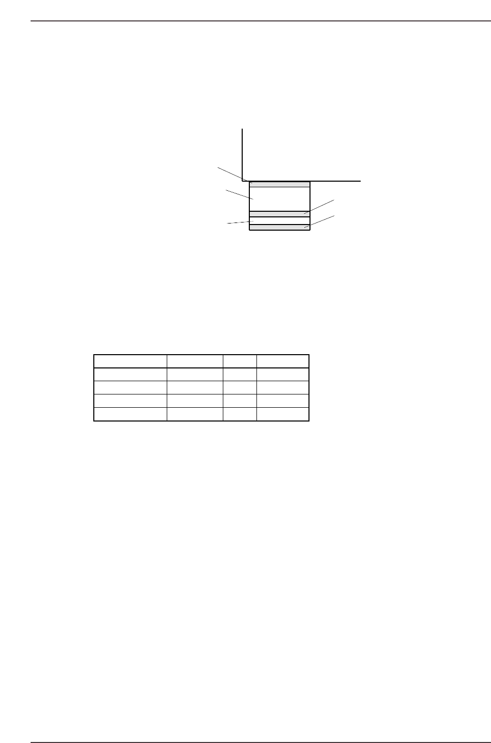
CP-642
Adhesive pad
Adhesive pad
Adhesive pad
Vibration proofing unit
Adjusting plate
CP6M11004
Part 10 Chapter 1 Vibration Reduction Unit
Edition 1.0 10-1-4 CP-6-series Mechanical Reference