CP-6-series Mechanical Reference.pdf - 第203页
3.5.2 Adjusting the Nozzle UP Limit and DOWN Limit Sensors The nozzle UP limit and DOWN limit sensors which detect the height of the nozzle UP/DOWN rod are mounted inside the cam box. Adjust the mounting positions of the…
4. Move the area for the removed axis to station 11, then use I/O (Y028 PLACE SOL
ON) to operate the lever.
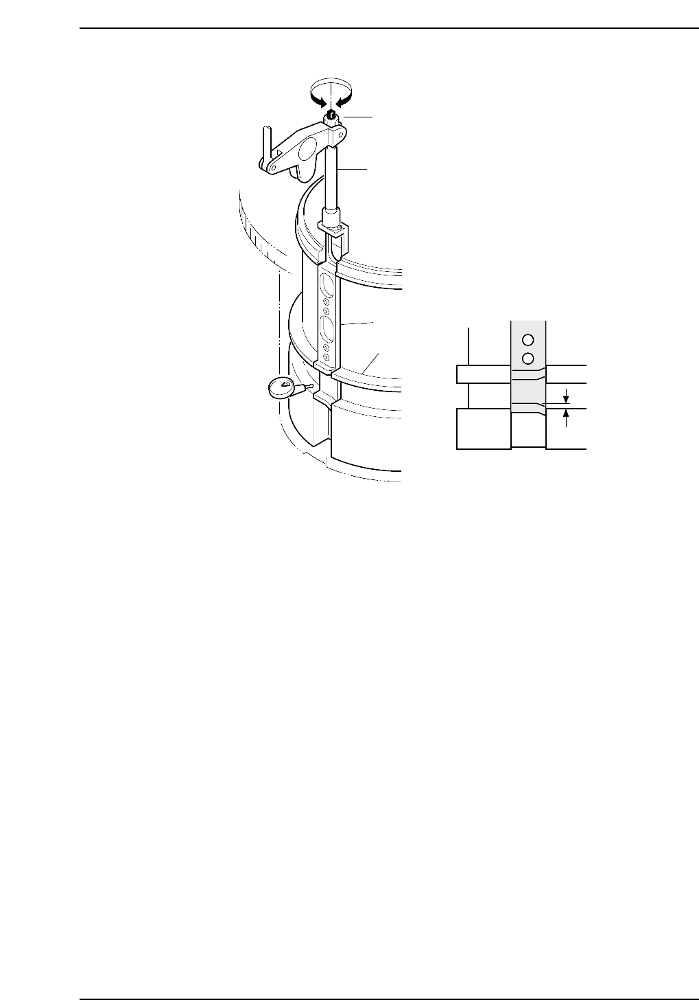
5. Set the cam angle within the range shown below, and position the dial gauge as
shown in the figure above.
• CP6-4000 = 313° ~ 53°• CP6-5000 = 308° ~ 75°
6. Adjust the rod so that there is 0 ±0.03 difference between the slider groove and the
fixed groove in the cam.
7. Reattach the nozzle shaft assembly in the original location.
Using the clutch alignment jig, reverse the removal procedures to attach the
assembly.
CP6M5045
0±0.03 mm
Adjustment bolt
Rod
Slider
Fixed barrel
cam
Part 5 Chapter 3 Station Adjustments
Edition 1.0 5-3-27 CP-6-series Mechanical Reference
3.5.2 Adjusting the Nozzle UP Limit and DOWN Limit Sensors
The nozzle UP limit and DOWN limit sensors which detect the height of the nozzle
UP/DOWN rod are mounted inside the cam box. Adjust the mounting positions of
these sensors so that they switch ON when the nozzle is at its UP limit and DOWN limit
positions.
WARNING
• Turn off the 200 V servo power before carrying out this work.
• Exercise extreme caution when working on the machine if the cam is
not at its origin (0 deg.). Recoil of the cam axis can endanger the
operator.
Nozzle UP Limit Sensor
1. Set the cam axis at the 0-degree position.
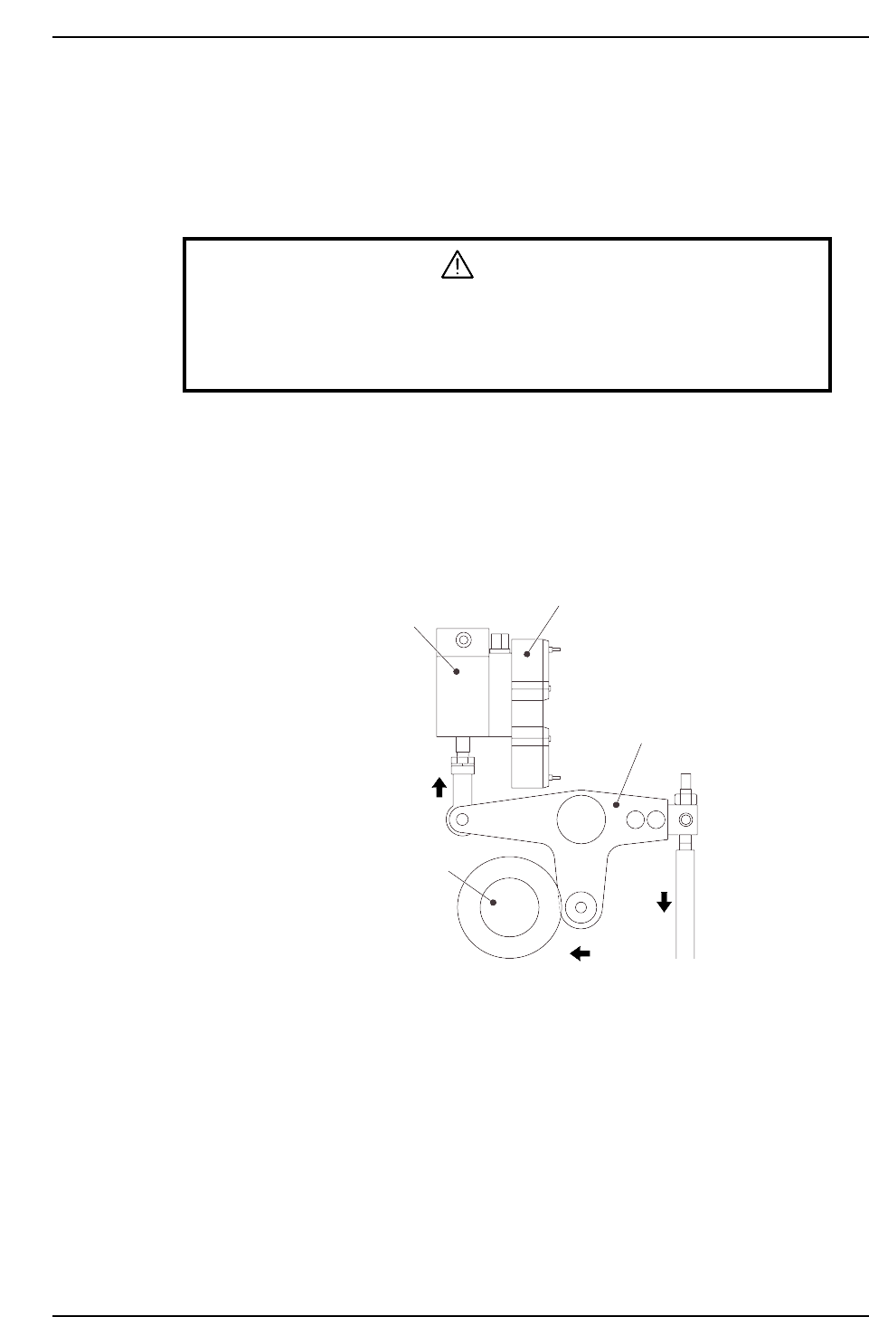
2. Execute the following I/O commands to pull in the ST11 placing stop cylinder
(located in the cam box):
[SET] - [MANUAL] - [I/O] - [Standard I/O] - [OUTPUT] -> Y028 PLACE SOL ON
The cam lever will then follow the cam axis.
Solenoid valve
ST11 placing stop cylinder
Cam lever
Cam axis
CP6M5046
Part 5 Chapter 3 Station Adjustments
Edition 1.0 5-3-28 CP-6-series Mechanical Reference
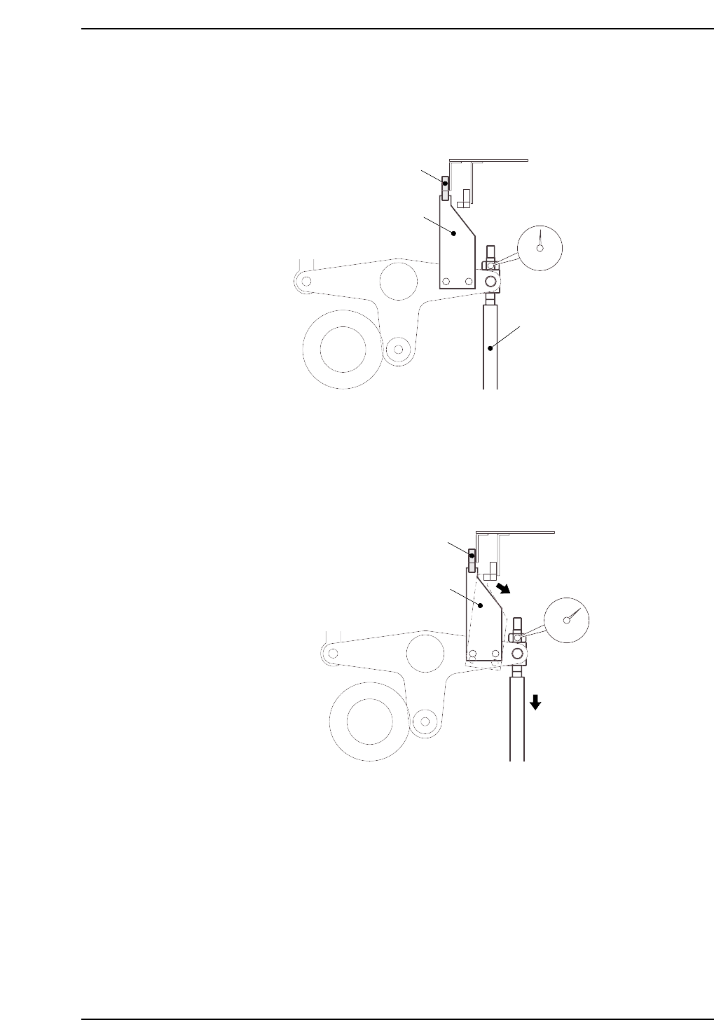
3. Place a dial gauge on the nozzle UP/DOWN rod and set the gauge reading to “0”.
In this condition, the cam axis will be at its 0-degree position, and the nozzle
UP/DOWN rod will be at its UP limit position. Verify that the nozzle UP limit
sensor is ON (I/O INPORT X06B ST11 UP POS is ON).
4. While observing the dial gauge, rotate the cam axis in the forward direction to
lower the nozzle UP/DOWN rod. Adjust the sensor’s mounting position so that
the sensor switches OFF (I/O INPORT X06B ST11 UP POS switches OFF) when
the rod has been lowered 0.3 to 0.4 mm.
CP6M5048
Nozzle UP limit sensor OFF
Dog
Rod lowered
0.3 to 0.4 mm
CP6M5047
Nozzle UP limit sensor ON
Dog
Nozzle UP/DOWN rod
Set dial gauge to “0”
Part 5 Chapter 3 Station Adjustments
Edition 1.0 5-3-29 CP-6-series Mechanical Reference