CP-6-series Mechanical Reference.pdf - 第42页
The Workings of the Cam The cam box consists of nine cams, two cylinder cams and two index units. The purpose of these items are explained here. The Nine Cams The nine cams are used in the operation of the feeders and pl…
2.1 Parts Mounting System
2.1.1Cam Box
The cam box, located on the upper part of the CP-6, consists of two camshafts, a central
axis, two cam axes, cam levers, air cylinders, two index units and the cam motors that
operate these units. The cam motor is responsible for operating all mechanical station
and feeder functions.
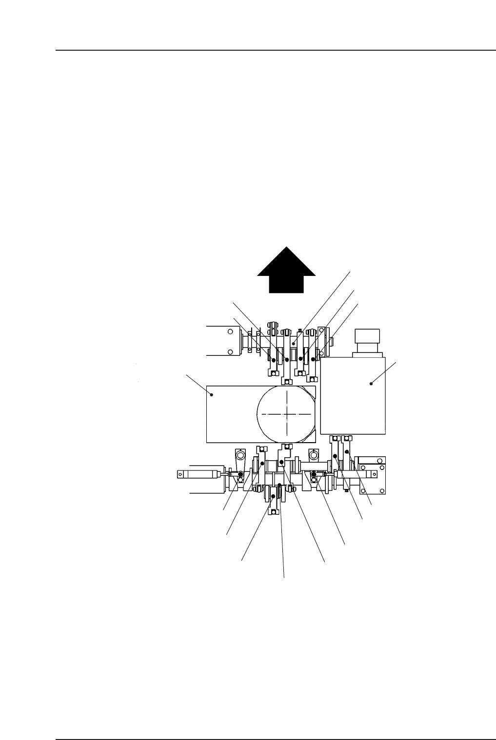
Cam Location
Refer to the figure below for the schematic of the cams and shafts inside of the cam box.
Machine Front
Cam axis A
Theta index unit
Cam axis B
Nozzle index unit
CP6M1011Ea
Station 12 FR θ clutch up/down
Station 13 PR θ clutch up/down
Station 11 nozzle up/down
Station 10 F θ clutch up/down
Station 3 P θ R/L
Station 3 P θ clutch up/down
Station 1 feeder advance
Station 1 waste tape cut
Station 18 change clutch
up/down
Station 13 PR θ R/L
Station 1 nozzle up/down
Part 1 Chapter 2 Functions of Each Component
Edition 1.1 1-2-2 CP-6-series Mechanical Reference
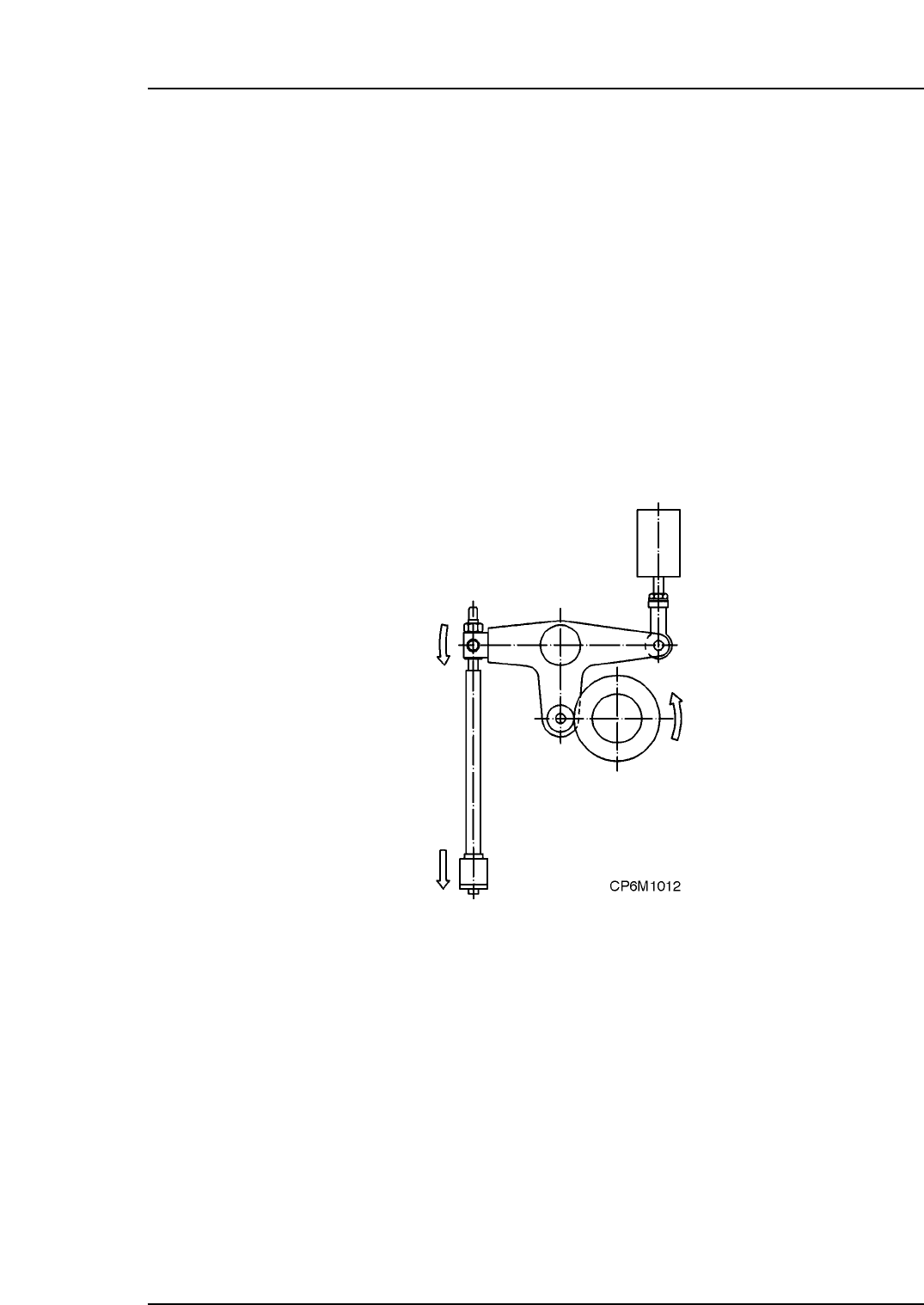
The Workings of the Cam
The cam box consists of nine cams, two cylinder cams and two index units. The purpose
of these items are explained here.
The Nine Cams
The nine cams are used in the operation of the feeders and placing heads.
• Station 1 nozzle up/down (also Station 1 mechanical valve change)
• Station 1 feeder tape advance
• Station 1 waste tape cutter (also Station 16 mechanical valve change)
• Station 3 pre-theta clutch up/down
• Station 10 fine-theta clutch up/down (also Station 5 positioning)
• Station 11 nozzle up/down (also Station 11 mechanical valve change)
• Station 12 fine-theta reverse clutch up/down
• Station 13 pre-theta reverse clutch up/down
• Station 18 nozzle change
Part 1 Chapter 2 Functions of Each Component
Edition 1.1 1-2-3 CP-6-series Mechanical Reference
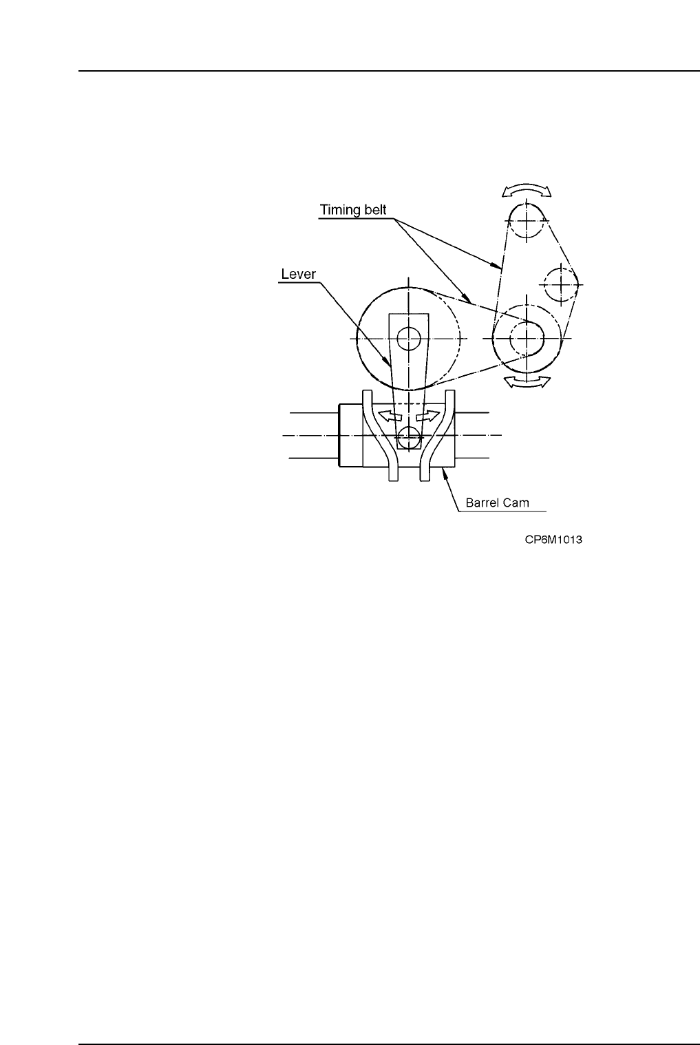
The Barrel Cam
The barrel cam is used for performing station 3 pre-theta as well as station 13 pre-theta
reverse. Through the operation of the barrel cam, the nozzle is accurately rotated ±90°.
2.1.2The Index Units
Nozzle Index Unit
The Nozzle Index Unit is situated in the center of the cam box and is responsible for
rotating the cam turret, to which the lower half of the nozzle shaft is attached.
Theta Index Unit
Facing the machine from the front, the Theta Index Unit is situated on the left hand side
of the cam box and is responsible for rotating the small helical gear which in turn rotates
the larger helical gear. This larger gear rotates the upper half of the nozzle shaft. Speed
is enhanced by rotating the top half and the bottom half of the shaft independantly.
Part 1 Chapter 2 Functions of Each Component
Edition 1.1 1-2-4 CP-6-series Mechanical Reference