CP-6-series Mechanical Reference.pdf - 第53页
2.3 Vision System 2.3.1 Parts Cameras This system includes a wide and a narrow CCD camera, frontlighting and backlighting system, a CCD camera mounting bracket and other related parts. These cameras perform vision inspec…
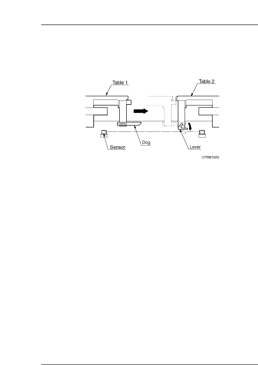
Preventing Device Table Collisions
Since the two device tables work independently, an interlock is used to prevent collisions
when they are working in close proximity to each other.
Two types of interlock systems are used. One is controlled using the software and the
other is controlled using the mechanical unit (sensor detection).
The sensor detection interlocking system is depicted in the following figure.
When the tables approach each other, a dog presses down on a lever. This lever
interrupts the sensor beam causing the machine to stop.
2.2.3Tape Cutter
Located behind the placing head at station 1 a vertical blade cuts against a ridge to cut
any tape which has extended past the end of the feeder.
The waste tape gets sucked through a vacuum hose into the waste tape collection box at
the rear of the machine.
2.2.4Pallet Feeder (Only for the CP-652C)
This device is used to transport pallets loaded with tape feeders.
It is composed of the pallets, setup stations, elevators, return conveyor, and related parts.
Pallets: All tape feeders are loaded on pallets for transport.
D-axis carrier: This transports pallets on the D-axis. This unit is driven by
the servo-motor to the position specified in the placing
program.
Setup stations: This unit facilitates removal or placement of tape feeders by
the operator.
Elevators: Elevators are of two types: for lifting and for lowering.
A pallet lifted by elevator is transferred to the D-axis. A
pallet lowered by elevator is transported to the return
conveyor.
Return conveyor: This conveyor transports pallets from the out-side to the in-
side.
Pallet pushers: This is driven by a pneumatic cylinder.
A pallet on an in-elevator is pushed toward the in-side setup
station, and a pallet on the D-axis carrier is expelled toward
the out-side setup station.
Part 1 Chapter 2 Functions of Each Component
Edition 1.1 1-2-13 CP-6-series Mechanical Reference

2.3 Vision System
2.3.1Parts Cameras
This system includes a wide and a narrow CCD camera, frontlighting and backlighting
system, a CCD camera mounting bracket and other related parts.
These cameras perform vision inspection of individual parts for the purpose of placing
position and angular compensation, etc.
2.3.2Mark Read Camera
This system includes a CCD camera, light, CCD camera mounting bracket and related
parts.
The camera reads the fiducial marks on the board to perform corrections to the position
of the board.
Part 1 Chapter 2 Functions of Each Component
Edition 1.1 1-2-14 CP-6-series Mechanical Reference
2.4 Board Conveyance
In-conveyor
The in-conveyor consists of guide rails, a flat T-type conveyor belt, a conveyor-motor and
related items. The board is received from the previous production stage and fed onto the
XY-table.
Out-conveyor
The out-conveyor consists of guide rails, a flat T-type conveyor belt, a conveyor motor
and related items. The table receives boards which have had parts placed on them and
feeds them out of the machine to the next production stage.
Carrier Type Loading System (CP-643E/643ME only)
The CP-643 sequence loader uses board clamping units (carriers) to carry out the
transport of boards between the in-conveyor, main conveyor, and out-conveyor.
There are an in-carrier and out-carrier and these are driven by air cylinders in accordance
with the placing program.
In-conveyor: Boards on the in-conveyor are pushed up by the lifter and
the in-carrier retracts to receive the boards.
In-carrier: Boards are received from the in-conveyor and transported to
the main conveyor.
Main conveyor: The boards are clamped and the conveyor moves
subordinate to the XY-table.
Out-carrier: Boards are received from the main conveyor and transported
to the out-conveyor.
Out-conveyor: Boards are received from the out-carrier and transported out
of the machine.
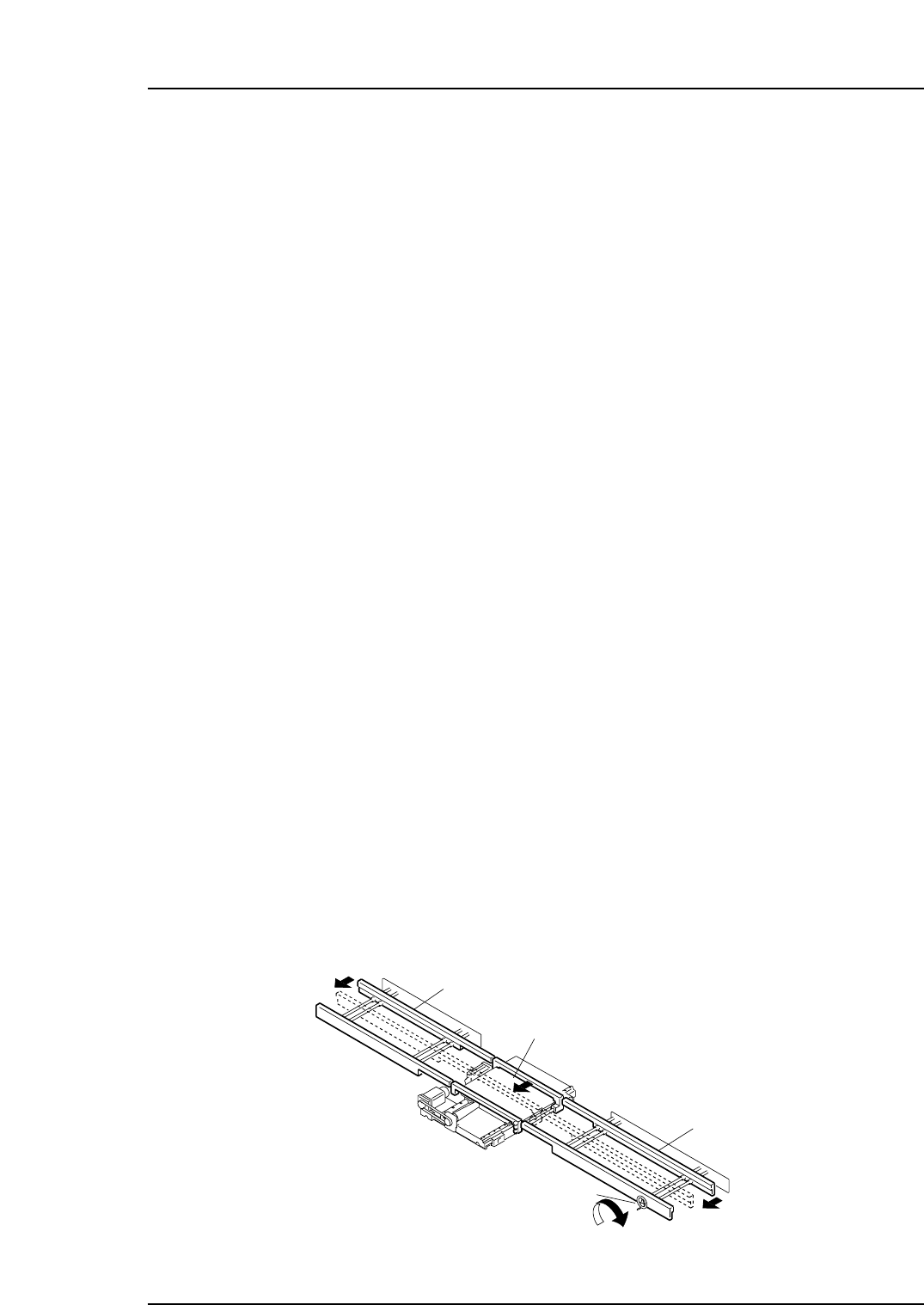
Conveyor Adjustment (except for CP-643E/643ME)
Refer to Part 9, Chapter 1 “Carrier Type Loading System” for CP-643E/643ME.
The board in production is transported through the in-conveyor, XY-table and out-
conveyor.
When the in-conveyor and out-conveyor are joined by raising the XY-table to its loading
position, the width of all three can be changed at the same time by turning the handle
located on the out-conveyor.
Refer to Part 2, Chapter 1 “Changing the Conveyor Width”.
In-conveyor
XY-table
Out-conveyor
Handle
Turn to the right
Conveyor width
becomes narrow
CP6M1026
Part 1 Chapter 2 Functions of Each Component
Edition 1.1 1-2-15 CP-6-series Mechanical Reference