CP-6-series Mechanical Reference.pdf - 第43页
The Barrel Cam The barrel cam is used for performing station 3 pre-theta as well as station 13 pre-theta reverse. Through the operation of the barrel cam, the nozzle is accurately rotated ± 90°. 2.1.2 The Index Units Noz…
The Workings of the Cam
The cam box consists of nine cams, two cylinder cams and two index units. The purpose
of these items are explained here.
The Nine Cams
The nine cams are used in the operation of the feeders and placing heads.
• Station 1 nozzle up/down (also Station 1 mechanical valve change)
• Station 1 feeder tape advance
• Station 1 waste tape cutter (also Station 16 mechanical valve change)
• Station 3 pre-theta clutch up/down
• Station 10 fine-theta clutch up/down (also Station 5 positioning)
• Station 11 nozzle up/down (also Station 11 mechanical valve change)
• Station 12 fine-theta reverse clutch up/down
• Station 13 pre-theta reverse clutch up/down
• Station 18 nozzle change
Part 1 Chapter 2 Functions of Each Component
Edition 1.1 1-2-3 CP-6-series Mechanical Reference
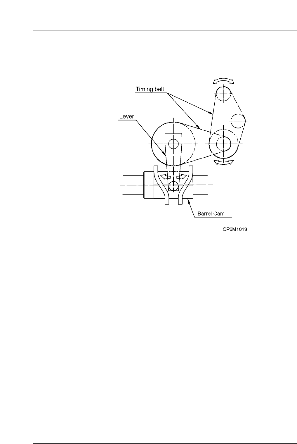
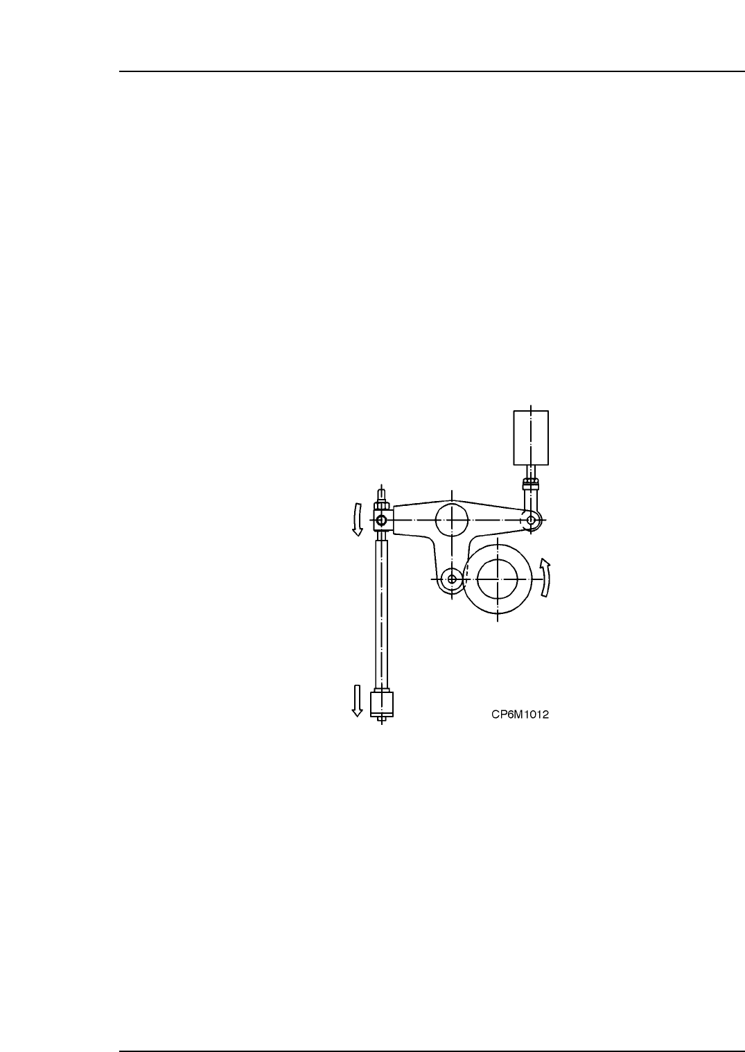
The Barrel Cam
The barrel cam is used for performing station 3 pre-theta as well as station 13 pre-theta
reverse. Through the operation of the barrel cam, the nozzle is accurately rotated ±90°.
2.1.2The Index Units
Nozzle Index Unit
The Nozzle Index Unit is situated in the center of the cam box and is responsible for
rotating the cam turret, to which the lower half of the nozzle shaft is attached.
Theta Index Unit
Facing the machine from the front, the Theta Index Unit is situated on the left hand side
of the cam box and is responsible for rotating the small helical gear which in turn rotates
the larger helical gear. This larger gear rotates the upper half of the nozzle shaft. Speed
is enhanced by rotating the top half and the bottom half of the shaft independantly.
Part 1 Chapter 2 Functions of Each Component
Edition 1.1 1-2-4 CP-6-series Mechanical Reference
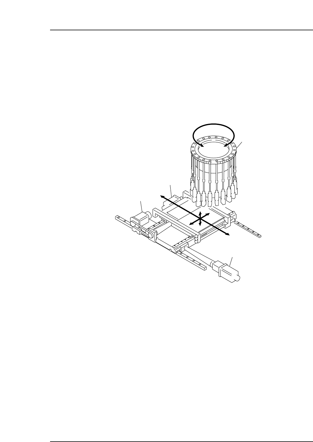
2.1.3XY-Table (Main Conveyor)
The XY table consists of the X, Y and Z-axis servo motors, the X and Y-axis guide rails,
the back-up plate and related items.
In addition to movements in the X- and Y-axes, the XY-table also moves vertically (by
means of the Z-axis motor) to adjust itself automatically to the height of the part being
placed. The X- and Y-motors can move in increments of 0.01 mm. The Z-motor moves in
increments of 0.002 mm.
CP-6/6E, CP-6M/6ME
Z-axis servo motor
Y-axis servo motor
X-axis servo motor
Turret
CP6M1014E
Part 1 Chapter 2 Functions of Each Component
Edition 1.1 1-2-5 CP-6-series Mechanical Reference