CP-6-series Mechanical Reference.pdf - 第81页
3. Setting the Back-up Pins Point Position the back-up pins in accordance with the shape and size of the board being produced considering the position of any parts that are pre-mounted on the underside of the board. When…
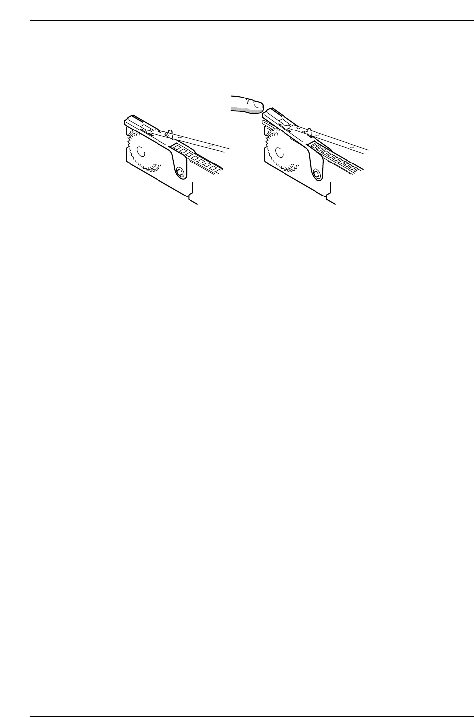
3. Use the appropriate feeder type according to part type.
Incompatible part tape makes it impossible to close the tape leaf correctly.
CP6M2003
Correct Incorrect
Part 2 Chapter 2 Feeder Setting
Edition 1.0 2-2-2 CP-6-series Mechanical Reference
3. Setting the Back-up Pins
Point
Position the back-up pins in accordance with the shape and size of the board being
produced considering the position of any parts that are pre-mounted on the underside of
the board.
When possible, back-up pins or rubber blocks (shock-free back-up; CP-642/643 series
only) should be used to ensure stable placing accuracy.
Procedure
1. Execute the following command operation to move the XY-table to the loading
position. [LOADER] - [LOADING PSTN] - START button.
2. Press [LIFTER ▲] - START button to raise the XY-table.
3. Press the EMERGENCY STOP button.
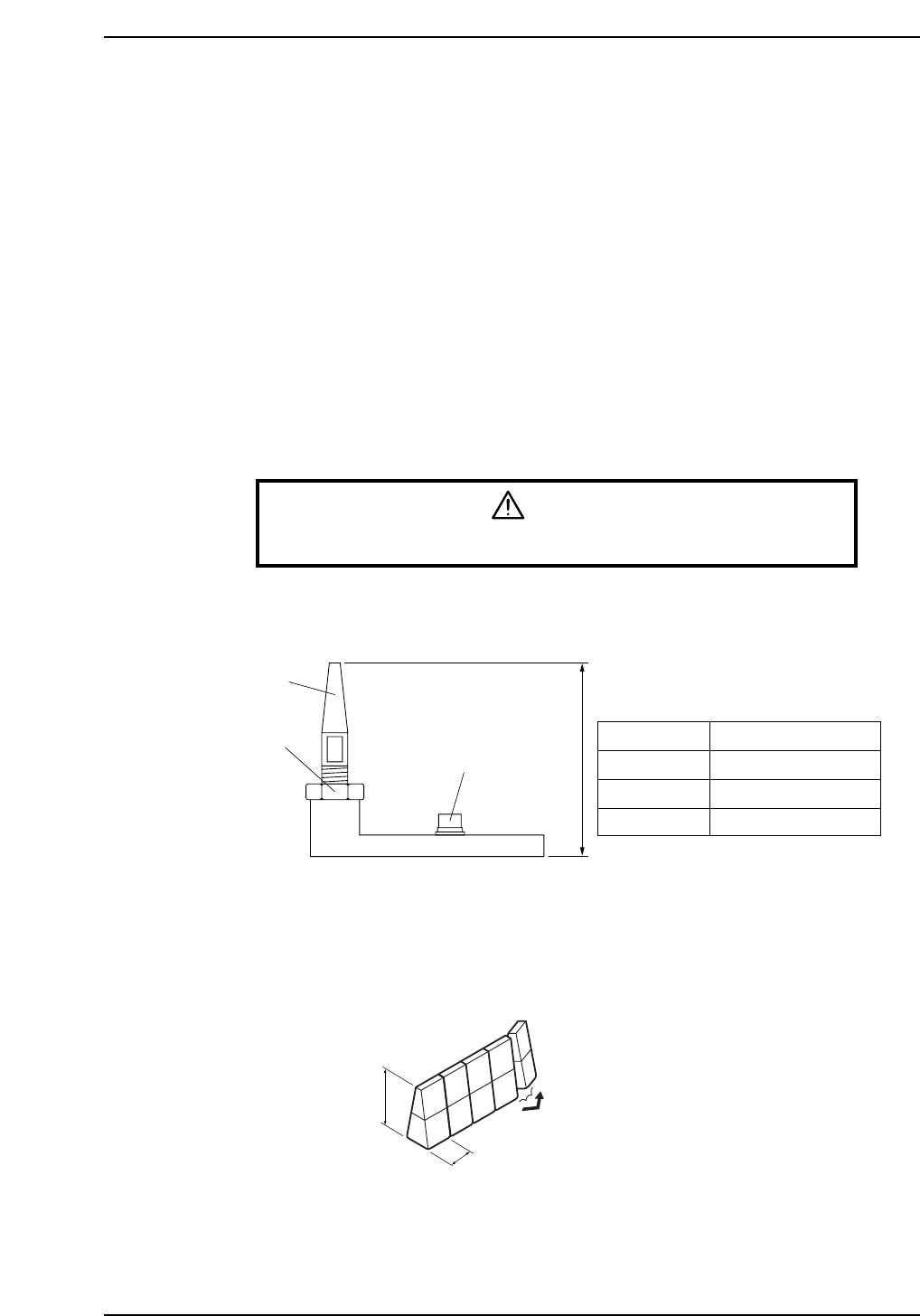
WARNING
Turn off the 200 V servo power before carrying out this work.
4. Set the back-up pin to the specified height as shown in the figure below.
When using rubber blocks (CP-642/643 series only):
Cut the rubber block into segments of the required length, and affix the segments
to the plate using double-sided tape.
CP6M2005
20 mm
39.2 mm
Part name: Shock free back-up
Part No.: CSSZ0550
Mounting screw
Bottom surface of board
Top surface of back-up pin plate
Pin
Lock nut
CP6M2004
Models
CP-6
CP-642/643
CP-65/652C
Reference value (mm)
41 – (Board thickness)
39.2
37
Back-up pin height
Part 2 Chapter 3 Setting the Back-up Pins
Edition 1.0 2-3-1 CP-6-series Mechanical Reference
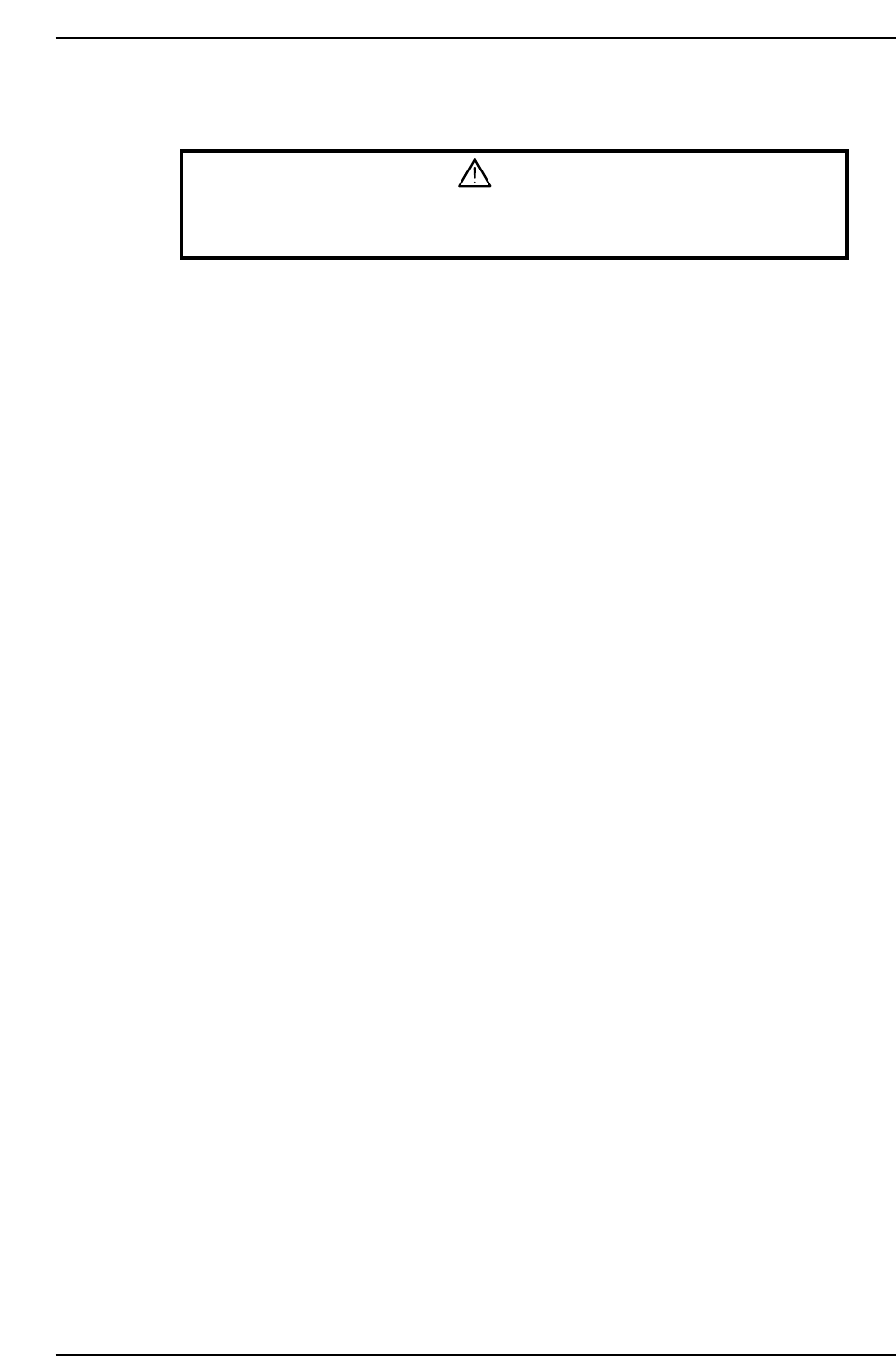
5. Taking the position of pre-mounted parts into consideration, position the backup
pins such that the board is evenly supported.
CAUTION
Do not set any back-up pins under the movable rail. The back-up pin
will collide with the rail when the back-up pin plate is lifted up.
6. Cancel the EMERGENCY STOP status.
Press [LIFTER ▼] - START button to lower the XY-table.
7. Perform the load and unload board operation to confirm that the height and
position of the back-up pin is suitable to support the board.
Part 2 Chapter 3 Setting the Back-up Pins
Edition 1.0 2-3-2 CP-6-series Mechanical Reference