CP-6-series Mechanical Reference.pdf - 第198页
3.3 Station 3 Pre-theta Station 3 rotates the nozzles with parts picked up at station 1 approximately -90 ° , 0 ° or +90 ° depending on the settings in the placement program. 3.3.1 Clutch Meshing Check W ARNING • Turn of…
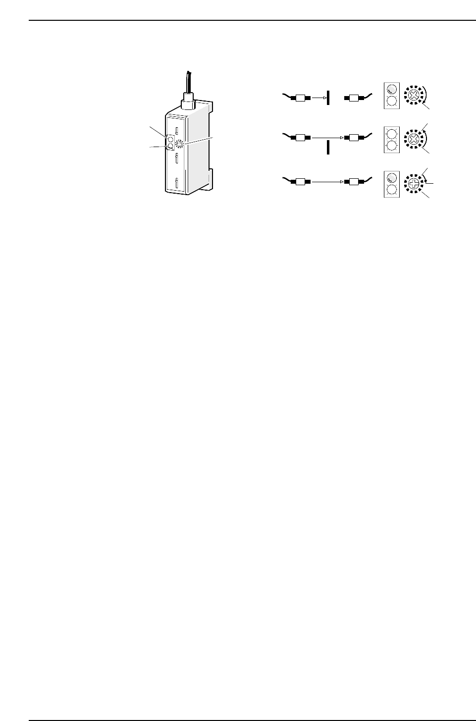
Sensor Sensitivity Adjustment
1. Break the light beam with a ruler (or something similar) and rotate the amplifier
trimmer to the right until the red LED (A) goes out.
2. Remove the ruler and rotate the trimmer to the left until the red LED (B) lights up.
3. Return the trimmer to a location between (A) and (B).
Red LED
Green LED
Trimmer
(1)
(2)
(3)
SET
(A)
(B)
(B)
(A)
CP6M5040
Part 5 Chapter 3 Station Adjustments
Edition 1.0 5-3-22 CP-6-series Mechanical Reference
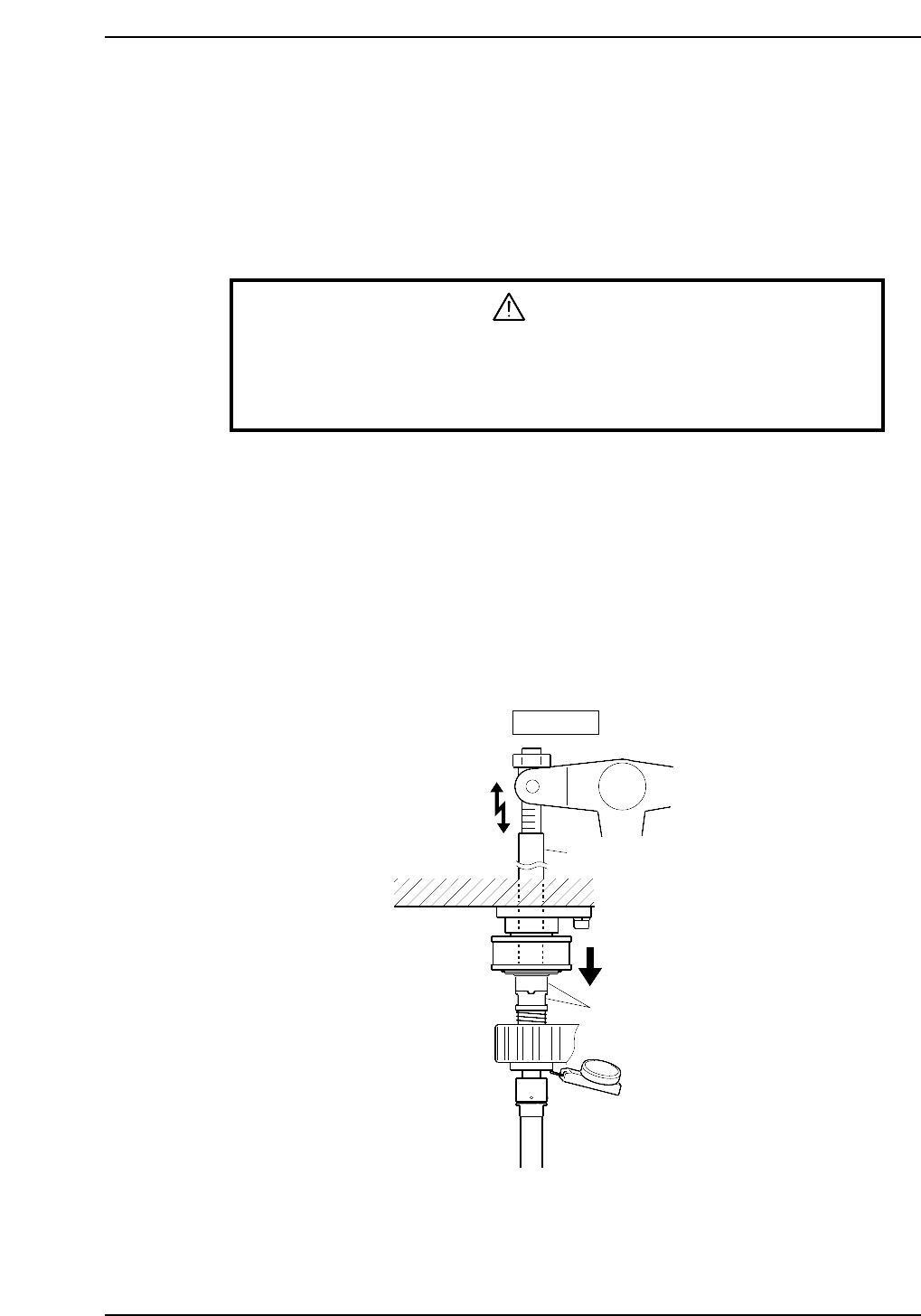
3.3 Station 3
Pre-theta
Station 3 rotates the nozzles with parts picked up at station 1 approximately -90°, 0° or
+90° depending on the settings in the placement program.
3.3.1 Clutch Meshing Check
WARNING
• Turn off the 200 V servo power before carrying out this work.
• Exercise extreme caution when working on the machine if the cam is
not at its origin (0 deg.). Recoil of the cam axis can endanger the
operator.
Perform this check on the low-pressure nozzle.
1. Rotate the cam to 0°, turn on the pre-rotation solenoid (Y022 PQ ROT SOL ON) for
station 3 to operate the lever.
2. Set the dial gauge to the bottom of the nozzle shaft brake.
3. Use the cam handle to rotate the cam to 200°.
4. Ensure that the clutches mesh properly and the nozzle shaft assembly deflects the
dial gauge 0.3 ~ 0.35 mm as illustrated below.
Note: The low-pressure nozzle refers to the nozzle axis (out of the 20) that receives the weakest
pushing pressure. Use the low-pressure nozzle for meshing checks at stations 3, 5, 10, 12
and 13.
Station 3
Rod
Clutches
0.30 ~ 0.35 mm
CP6M5041
Part 5 Chapter 3 Station Adjustments
Edition 1.0 5-3-23 CP-6-series Mechanical Reference
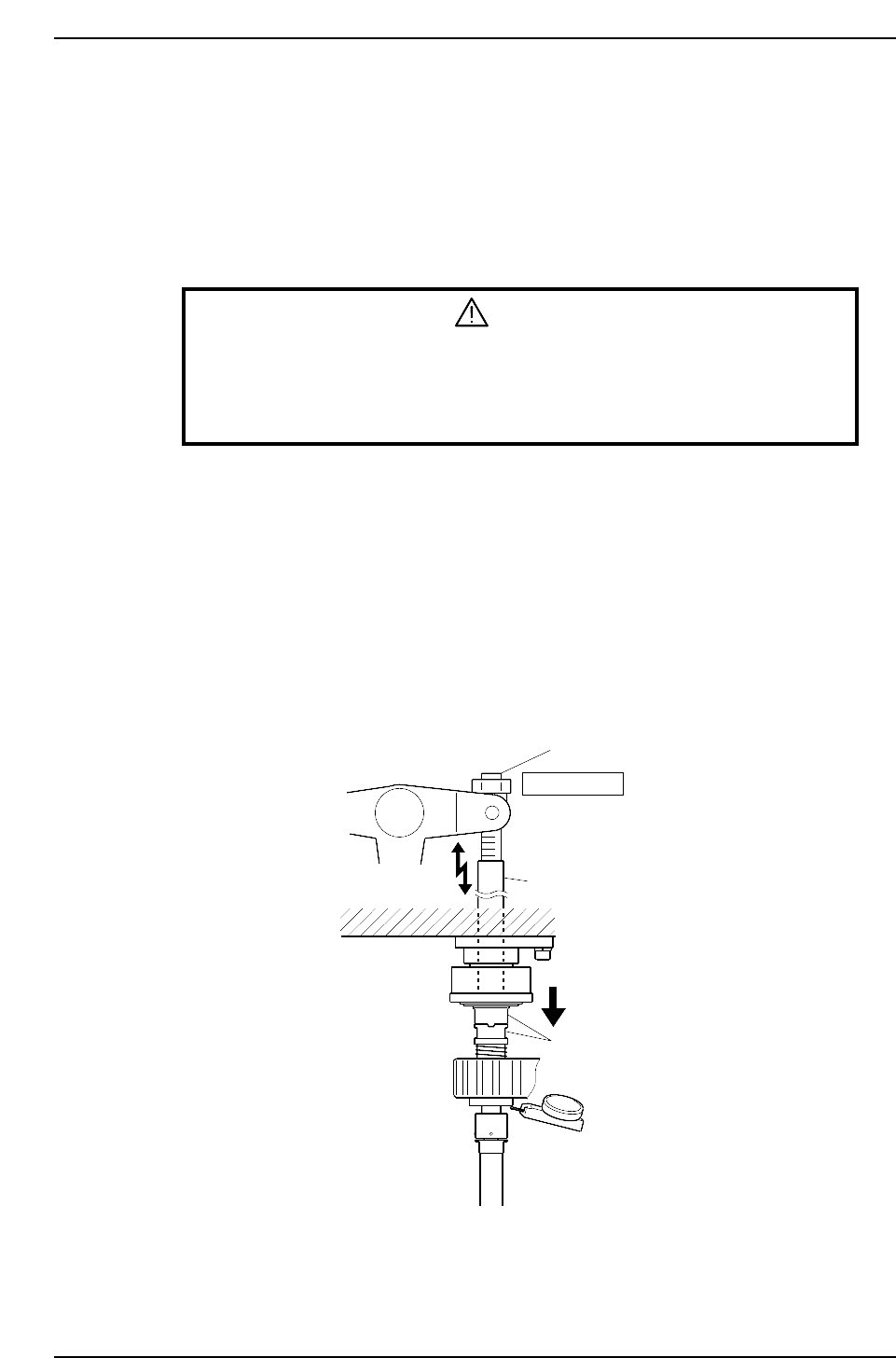
3.4 Station 10
Fine-theta
Station 10 refers to the vision processing data and rotates a part the remaining angle for
placement.
3.4.1 Clutch Meshing Check
WARNING
• Turn off the 200 V servo power before carrying out this work.
• Exercise extreme caution when working on the machine if the cam is
not at its origin (0 deg.). Recoil of the cam axis can endanger the
operator.
1. Rotate the cam to 0°, turn on the fine-rotation solenoid (Y030 Fθ SOL ON) for
station 10 to operate the lever.
2. Set the dial gauge to the bottom of the nozzle shaft brake.
3. Use the cam handle to rotate the cam to 200°.
4. Ensure that the clutches mesh properly and the pressure applied to the low nozzle
is 0.3 ~ 0.35 mm.
5. Perform this check for all of the nozzle axes.
Note: The low-pressure nozzle refers to the nozzle axis (out of the 20) that receives the weakest
pushing pressure. Use the low-pressure nozzle for meshing checks at stations 3, 5, 10, 12
and 13.
Adjustment bolt
Station 10
Rod
Clutches
0.30 ~ 0.35 mm
CP6M5042
Part 5 Chapter 3 Station Adjustments
Edition 1.0 5-3-24 CP-6-series Mechanical Reference