CP-6-series Mechanical Reference.pdf - 第268页
Notes: Part 8 Chapter 4 Elevators Edition 1.0 8-4-6 CP-6-series Mechanical Reference
5. Mount the lowering stop sensor at this position, adjust the position of the dog so
that the relationship shown in the figure above is obtained, and secure in place
with the bolt.
6. Next, perform inching to raise the lifter.
7. Stop operation before the lifter reaches its highest position.
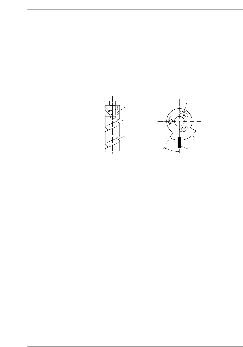
8. While monitoring the position of the cam follower moving within the groove on
the ball screw, raise the lifter further.
9. The cam follower reaches the horizontal (flat) surface of the cam groove.
Stop the lifter at a point intermediate between this position and the stopper.
The flat surface described here refers to the surface that is perpendicular to the ball
screw.
10. Mount the rising stop sensor at this position, adjust the position of the dog so that
the relationship shown in the figure above is obtained, and secure in place with
the bolt.
30
Ball screw
Cam groove
Stopper
Position
where stopped
Flat surface
Cam follower
Bolt
Dog
Rising stop sensor
°
CP6M9027
Part 8 Chapter 4 Elevators
Edition 1.0 8-4-5 CP-6-series Mechanical Reference

Notes:
Part 8 Chapter 4 Elevators
Edition 1.0 8-4-6 CP-6-series Mechanical Reference
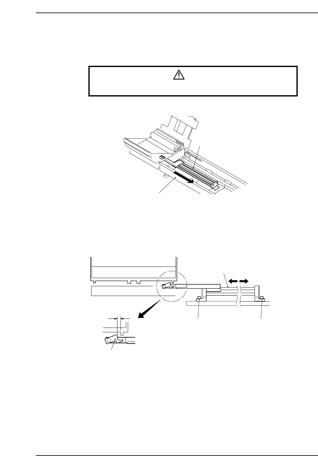
5. Return Conveyors
5.1 Adjustment of the Pallet Intake Cylinder
Warning
Turn off the 200 V servo power before carrying out this work.
1. Place a pallet on the "down" lifter and lower the lifter.
2. At the fully retracted position of the pallet intake cylinder, adjust the location of
the cylinder so as to obtain a clearance of 5 to 10 mm between the tab and the hook
on the bottom of the pallet, then secure in place with the bolts.
5-10 mm
Pallet
Pneumatic cylinder
Securing bolt Securing bolt
Tab
CP6M9029
Pallet intake cylinder
Return conveyor
CP6M9028
Part 8 Chapter 5 Return Conveyors
Edition 1.0 8-5-1 CP-6-series Mechanical Reference