CP-6-series Mechanical Reference.pdf - 第88页
Notes: Part 2 Chapter 4 Board Positioning Pins Edition 1.0 2-4-6 CP-6-series Mechanical Reference
<5000 type>
1. Press [LOADER] - [LOADER PSTN] followed by the START button to move the
XY-table to the loading position.
2. Press [LIFTER ▲]to raise the XY-table to the same height as the in/out-conveyor.
3. Press the EMERGENCY STOP button.
WARNING
Turn off the 200 V servo power before carrying out this work.
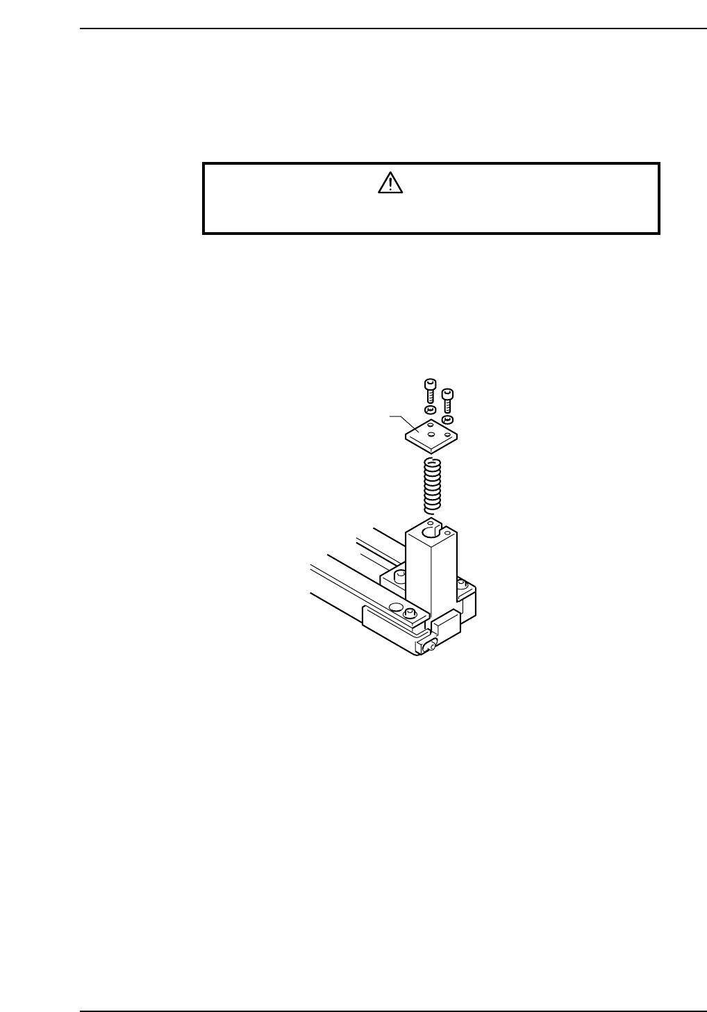
4. Unscrew the pin holder bolts.
5. Remove the pin and holder from the block. Be careful that the spring beneath the
pin does not shoot the pin out.
6. With the spring in place, put the cover on the reference pin block.
7. It is not necessary to remove the follow-up pin. Position the pin outside the size of
the board that is being produced.
Cover
CP6M2011
Part 2 Chapter 4 Board Positioning Pins
Edition 1.0 2-4-5 CP-6-series Mechanical Reference

Notes:
Part 2 Chapter 4 Board Positioning Pins
Edition 1.0 2-4-6 CP-6-series Mechanical Reference
5. Table Height Adjustment (CP-642, CP-642M)
Point
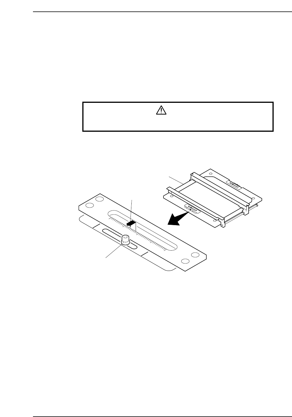
Use the slide levers at the front and rear of the XY-table to adjust the table for different
board thicknesses.
By using the slide levers, it is no longer necessary to adjust the height of the back-up pins
when a board of a different thickness is used.
Procedure
WARNING
Turn off the 200 V servo power before carrying out this work.
Loosen both lock screws (front and rear) and use the slide levers to adjust the table to the
thickness of the board. Ensure both slide levers are adjusted. Tighten the lock screws
when the adjustment is complete.
0
1
2
3
4
Lifter
Slide lever
Lock screw
CP6M2012
Part 2 Chapter 5 Table Height Adjustment
Edition 1.0 2-5-1 CP-6-series Mechanical Reference