CP-6-series Mechanical Reference.pdf - 第235页
6. Select [SET] → [SERVO] to view the Z-axis motor pulse count and then manually inch the Z-axis upwards until the dial gauge reads 0.3 mm. 7. Enter the resultant pulse count into Proper data. [SET] → [PROPER] → [D1/D2/Z…
1. Z-Axis Origin Position (Zθ)
In order to offset board warpage and minute deviations in nozzle shaft placing height, Zθ, the Z-axis
reference placing height, is calibrated in order that the board rises to make contact with the part being
held by the nozzle and then pushes up a further 0.3 mm.
1.1 Zθ Measurement (CP-642)
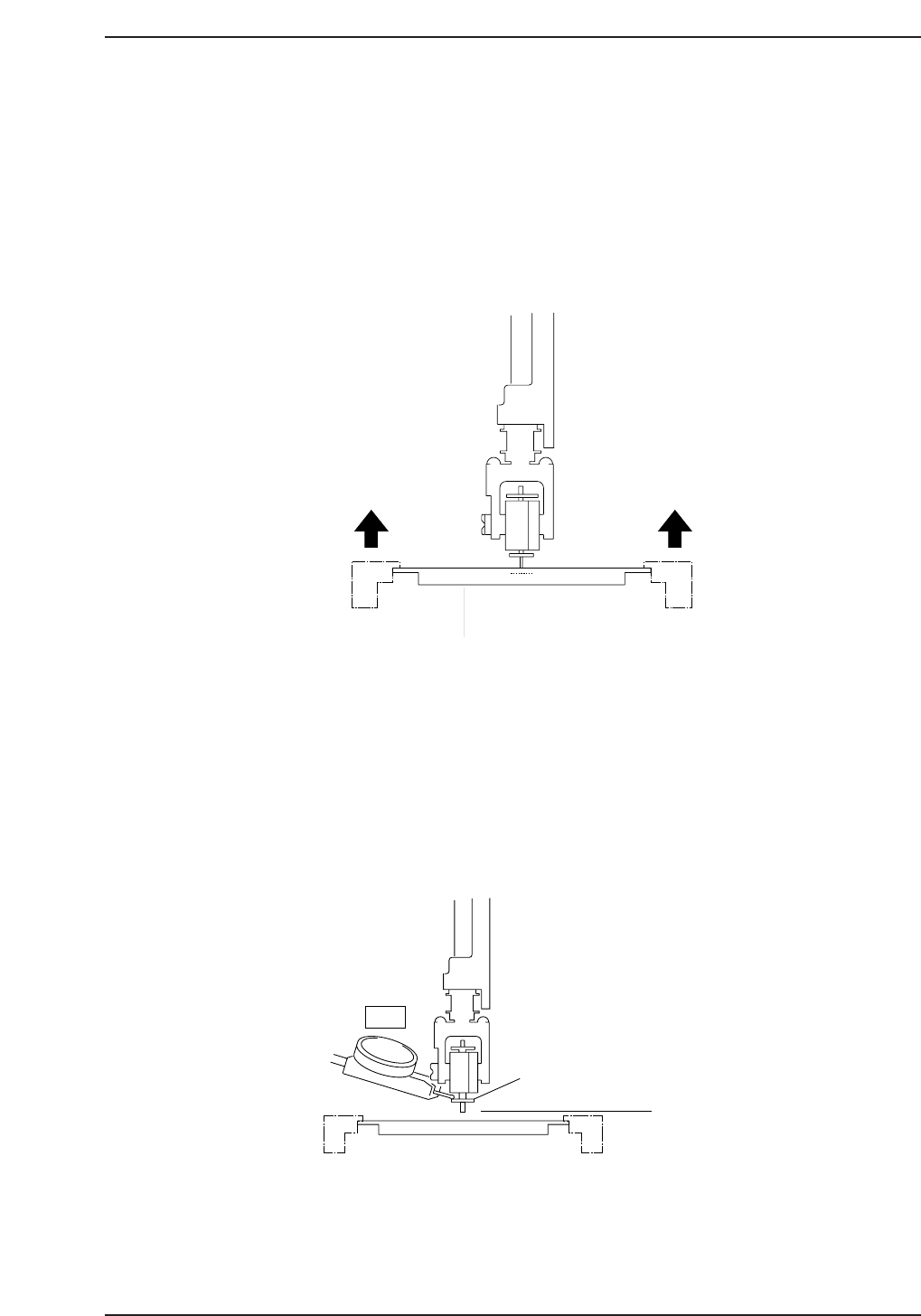
1. Load the fiducial jig-plate onto the main conveyor as shown in the diagram below.
2. Using the inching keys, move the fiducial plate under station 11.
3. Switch the I/O (Y028 PLACE SOL ON) to ON.
4. Rotate the cam angle to 200°, ensuring that the jig-plate is situated directly
underneath the nozzle shaft.
5. With a 20 mm diameter backlight-plate facing downward, place the dial gauge
needle on the upper surface of the backlight disk and set to zero.
"0"
Nozzle Lower
Limit
20 mm Backlight Plate
CP6M7002
Fiducial Jig-Plate
0.3 mm
0.3 mm
CP6M7001
Part 7 Chapter 1 Z-Axis Origin Position (Z
θ
)
Edition 1.5 7-1-1 CP-6-series Mechanical Reference
6. Select [SET] → [SERVO] to view the Z-axis motor pulse count and then manually
inch the Z-axis upwards until the dial gauge reads 0.3 mm.
7. Enter the resultant pulse count into Proper data.
[SET] → [PROPER] → [D1/D2/Z] → [ORIGIN] → [Zθ] → [SET].
8. Once the Zθ origin position has been registered at the machine side, ensure to
receive proper data to the host computer.
Note: When the machine is not in operation, there is nothing to prevent the XY-table damaging
the nozzle shaft at station 11. To avoid any unnecessary damage, always position the jig-
plate under station 11 when the cam angle is at 0°.
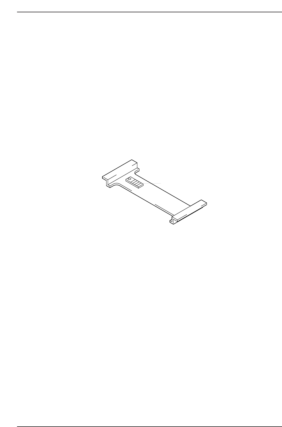
1.2 Zθ Adjustment (CP-643E)
Repeat the procedure for the CP-643E using the jig-plate below as opposed to the fiducial
jig-plate.
Note: The “-0.3 mm” spacer should be used for Z
θ
measurement
-0.3 mm
CP6M7003
Part 7 Chapter 1 Z-Axis Origin Position (Z
θ
)
Edition 1.5 7-1-2 CP-6-series Mechanical Reference

2. Placement Accuracy Measurement
PAM, an acronym for Placing Accuracy Measurement, is a measurement procedure used to calculate
and adjust the machine’s placing accuracy.
Note: Use of the machine for long periods without proper maintenance can reduce the original placing accuracy.
PAM can be used at such times to restore the placing accuracy to original levels.
PAM Kit
Please verify the contents of the PAM shipping container.
Overview
When PAM is started, a correction value for Station 11 (part placing station) Proper data
is calculated, and the ST11 Proper data is re-entered and saved in accordance with this
correction value. This data is also transmitted back to the host computer (F4G or MCS).
This ST11 Proper data acts to correct mechanical positional error (due to working and
mounting error amounts), resulting in a uniform correction. X and Y direction correction
values are entered for each nozzle. As the system consists of 20 heads with 6 nozzles per
head, this results in a total of 240 Proper data input items.
Item Name Quantity Model
Dummy parts for PAM 1 reel MPJ2220
Board for PAM 1 board K2096E(CP/IP/QP96-001)
Program FD disk for PAM 1 disk
Card ROM for PAM 1 card
Double-sided tape 1 roll Scotch Tape 666 25.4
CP6M7004
Part 7 Chapter 2 Placement Accuracy Measurement
Edition 1.0 7-2-1 CP-6-series Mechanical Reference