X7056_Operating manual_en.pdf - 第105页
Installation First use 105 Inspection system X7056 | Operating manual | Version 3.1 Rev.006| 2016-01-06 | 30.009.1930a 3. Start automatic operation, see „S tarting PCB inspection“ (Page 156). The PCB is automatically i…
Installation
First use
104
Inspection system X7056 | Operating manual |
Version 3.1 Rev.006| 2016-01-06 | 30.009.1930a
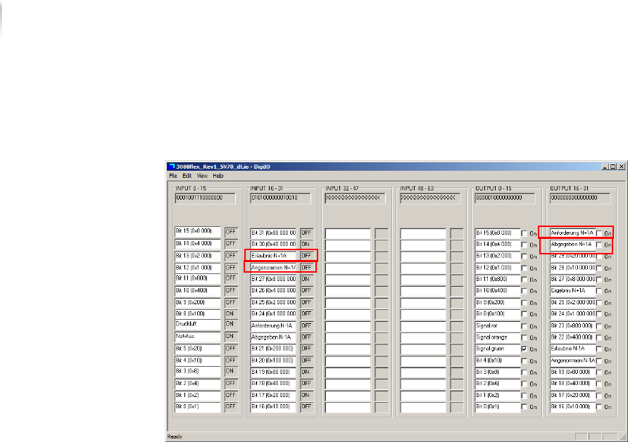
Checking
communication
with SV70
N+1A
Perform the following work steps:
1. Click S
TART > MAINTENANCE PROGRAM > DIGIIO.
2. Set the output signal N+1A Request to
ON.
The input signal N+1A permission changes to ON.
The transport conveyor of the external component starts.
3. Remove the PCB from the transport conveyor of the external
component.
4. Set the output signal N+1A Released to
ON and the output
signal N+1A Request to
OFF.
The input signal N+1A accepted changes to ON and the input
signal N+1A permission changes to OFF.
Communication with SV70 N+1A is checked.
The SV70 protocol is checked.
Checking the PCB transport
After the protocols are checked, check the function of the auto--
matic PCB transport.
Precondition: The SMEMA/SV70 protocols are checked.
Perform the following work steps:
1. Start the Viscom software, see „Starting the Viscom software“
(Page 155).
2. Select an inspection plan, see „Choosing an inspection
program“ (Page 156).

Installation
First use
105
Inspection system X7056 | Operating manual |
Version 3.1 Rev.006| 2016-01-06 | 30.009.1930a
3. Start automatic operation, see „Starting PCB inspection“ (Page
156).
The PCB is automatically infed, inspected, and outfed.
The PCB transport is checked.
Checking the calibration
To ensure that the cameras were not de-calibrated during trans--
port, the calibration must be checked.
Precondition: The pre-acceptance inspection program is loaded.
The PCB corresponding to the inspection program is fed in.
The fiducials are correctly located.
The pre-acceptance defect protocol is available.
ATTENTION
Faulty operation due to untrained personnel
Faulty inspection of the PCB.
Calibration may only be done by persons especially trained for
that purpose.
Perform the following work steps:
1. Start automatic operation, see „Starting PCB inspection“ (Page
156).
The PCB is automatically infed, inspected, and outfed.
2. Compare the detected defects with the defects from the pre-
acceptance defect protocol.
The detected defects correspond to the defects from the pre-
acceptance defect protocol.
? Significantly more defects are found?
The following causes are possible: the inspection program
settings are faulty, the PCB was incorrectly fed in or the
cameras are out of calibration.
The possible causes can be checked by a trained person; if
necessary, do a geometric calibration or grayscale value cali--
bration.
The calibration is checked.
Checking the network connections
Precondition: The inspection system is switched on.
The verification station/SPC server are connected and switched
on.
Installation
First use
106
Inspection system X7056 | Operating manual |
Version 3.1 Rev.006| 2016-01-06 | 30.009.1930a
Perform the following work steps:
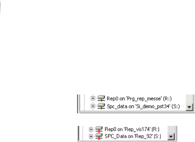
1. Open the Windows Explorer on the inspection system.
2. Check if the drives R: (verification station)/ S: (SPC server) are
connected.
The drives are connected.
The drives are not connected.
? The verification station/SPC server are connected and switched
on.
Switch on verification station/SPC-server.
Doubleclick drive R:/S: in Windows Explorer.
The network connections are checked.
Checking the data transfer to the verification station
Perform the following work steps:
1. Start the Viscom software, see „Starting the Viscom software“
(Page 155).
2. Select an inspection plan, see „Choosing an inspection
program“ (Page 156).
3. Start automatic operation, see „Starting PCB inspection“ (Page
156).
The PCB is automatically infed, inspected, and outfed.
4. Open the Windows Explorer on the inspection system.
5. Click D
RIVE R: > DATA > WORK.
The inspection system .res files are in the WORK directory.
The data transfer to the verification station is checked.
Checking the data transfer to the SPC server
Perform the following work steps:
1. Repeat steps 1 to 3.
2. Classify the found defects at the verification station.