X7056_Operating manual_en.pdf - 第151页
Operation Operating the safety feature s 151 Inspection system X7056 | Operating manual | Version 3.1 Rev.006| 2016-01-06 | 30.009.1930a Actuating EMERGENCY STOP Perform the following work steps: Pres s the EMERGENC Y …

Operation
Operating the safety features
150
Inspection system X7056 | Operating manual |
Version 3.1 Rev.006| 2016-01-06 | 30.009.1930a
Ending the
STOP mode
Perform the following work steps:
1. Close all the doors.
2. Press the ON button.
3. Choose the R
ESTART button on the STOP notice.
The axes initialize.
The inspection system is ready to operate.
4. Start the Viscom software, see „Starting the Viscom software“
(Page 155).
The AOI software starts.
The AXI software starts.
The STOP mode is ended.
EMERGENCY STOP
The EMERGENCY STOP button may only be actuated in emergen-
cies. A protective shroud around the button ensures that it is not
accidentally actuated.
The following themes are presented:
EMERGENCY STOP button
Actuating EMERGENCY STOP
Cancelling EMERGENCY STOP
EMERGENCY
STOP button
The EMERGENCY STOP button switches off all energies and poten-
tial risks in the system. The UPS maintains a power supply of 230
V to the system computer, take appropriate measures.
EMERGENCY STOP button

Operation
Operating the safety features
151
Inspection system X7056 | Operating manual |
Version 3.1 Rev.006| 2016-01-06 | 30.009.1930a
Actuating
EMERGENCY
STOP
Perform the following work steps:
Press the EMERGENCY STOP button.
The power to the inspection system is switched off.
The monitor is switched off.
the UPS ensures the regulated shutdown of the system
computer.
Release the PCB clamping manually, see „Releasing the PCB
clamping of the AXI transport track“ (Page 152).
EMERGENCY STOP has been actuated.
Cancelling
EMERGENCY
STOP
Perform the following work steps:
1. Turn the EMERGENCY STOP button clockwise to unlock it.
2. Turn on the UPS devices.
The axes initialize.
The inspection system is ready to operate.
3. Start the Viscom software, see „Starting the Viscom software“
(Page 155).
The AOI software starts.
The AXI software starts.
EMERGENCY STOP has been cancelled.
Releasing the PCB Clamping
To remove a PCB from the AOI or AXI transport during STOP or
EMERGENCY STOP states, release the PCB clamping manually.
The work steps in detail:
Releasing the PCB clamping of the AOI transport track
Releasing the PCB clamping of the AXI transport track
Releasing the
PCB clamping
of the AOI
transport
track
Precondition:
The STOP mode is actuated.
Operation
Operating the safety features
152
Inspection system X7056 | Operating manual |
Version 3.1 Rev.006| 2016-01-06 | 30.009.1930a
WARNING
Hazard of injury
Burns caused by the motors for the PCB clamping.
When loosening the PCB clamping, use only the handwheel.
Perform the following work steps:
1. Open the front lift door.
The hand wheel for releasing the PCB clamping is below the
AOI transport track.
2. Push the transport track completely to the left to reach the
hand wheel.
3. Release the PCB clamping:
Turn the hand wheel clockwise to release the PCB clamping.
The PCB clamping is released.
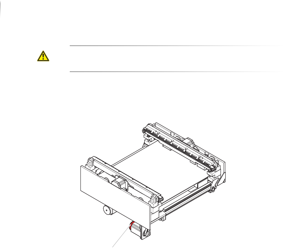
Releasing the
PCB clamping
of the AXI
transport
track
To remove a PCB from the AOI or AXI transport during STOP or
EMERGENCY STOP states, release the clamping manually.
Precondition: The STOP mode is actuated.
Handwheel