X7056_Operating manual_en.pdf - 第126页
Software Automatic mo de 126 Inspection system X7056 | Operating manual | Version 3.1 Rev.006| 2016-01-06 | 30.009.1930a Inspection details When one of the insp ections in the field T EST H ISTORY are chosen, its details…
Software
Automatic mode
125
Inspection system X7056 | Operating manual |
Version 3.1 Rev.006| 2016-01-06 | 30.009.1930a
Test history
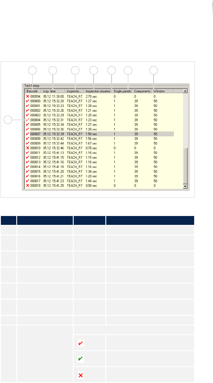
In the field TEST HISTORY, the last 50 inspected PCBs are displayed
in chronological order.
Field TEST HISTORY
Description of the field test history
No. Name Value Description
1 BARCODE - Displays the barcode of the PCB.
2 INSPECTION TIME - Displays the time the PCB was
inspected.
3 INSPECTION PLAN - Displays the inspection plan
names.
4 INSPECTION DURA-
TION
- Displays the analysis time
required.
5 SINGLE PANEL - Displays how many single panels
have defects.
6 COMPONENTS - Displays how many components
were inspected with defects.
7 WINDOW -
8 Inspection status Displays the result of the inspection.
PCB with defects.
PCB without defects.
Inspection aborted by user or
inspection system.
8
1 2 3 4 5 6 7
Software
Automatic mode
126
Inspection system X7056 | Operating manual |
Version 3.1 Rev.006| 2016-01-06 | 30.009.1930a
Inspection
details
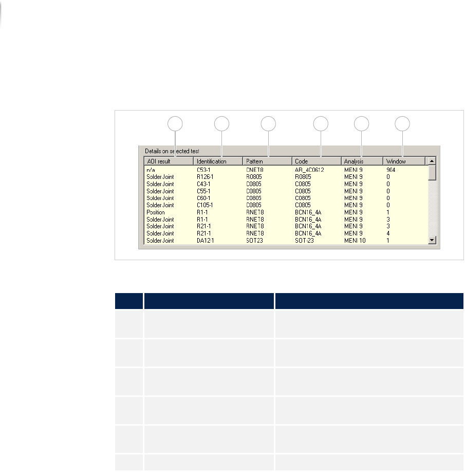
When one of the inspections in the field TEST HISTORY are chosen,
its details are displayed:
FieldINSPECTION DETAILS
Serial defect
The field SERIAL DEFECT is first available as of Version 7.38.
Description of the field "Inspection Details"
No. Name Description
1 AOI RESULT Displays the result from the inspection
system.
2 IDENTIFICATION Displays the ID of the corresponding
component.
3 PATTERN Displays the name of the component
type.
4 CODE Displays the component article
number.
5 ANALYSIS Displays the analysis process being
used.
6 WINDOW Displays the window number.
1 2 3 4 5 6
Software
Automatic mode
127
Inspection system X7056 | Operating manual |
Version 3.1 Rev.006| 2016-01-06 | 30.009.1930a
Defect distri-
bution
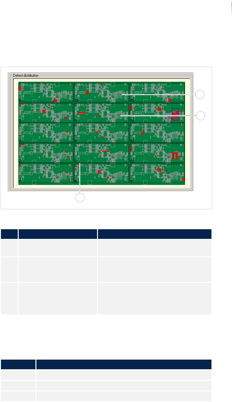
In the field DEFECT DISTRIBUTION, the entire PCB, all components,
the cameras and the defect frequency are displayed.
Field DEFECT DISTRIBUTION
The following keyboard commands are possible in the field DEFECT
D
ISTRIBUTION.
Description of the field "Defect Distribution"
No. Name Description
1 Display of the PCB Displays the schematic representation
of the PCB.
2 Cameras (can be config-
ured)
Displays the available cameras.
Active cameras are displayed in red;
inactive in blue
3 Defect distribution The colored-in components indicate
the frequency distribution.
White indicates the lowest defect
frequency, red indicates the highest.
Keyboard commands
Key Description
<NUM+> Enlarge overview image.
<NUM-> Shrink overview image.
<NUM*> Restore overview image.
1
2
3