X7056_Operating manual_en.pdf - 第42页
Product description System componen ts 42 Inspection system X7056 | Operating manual | Version 3.1 Rev.006| 2016-01-06 | 30.009.1930a XM sensor head with digital projector unit For additional information about technical …
Product description
System components
41
Inspection system X7056 | Operating manual |
Version 3.1 Rev.006| 2016-01-06 | 30.009.1930a
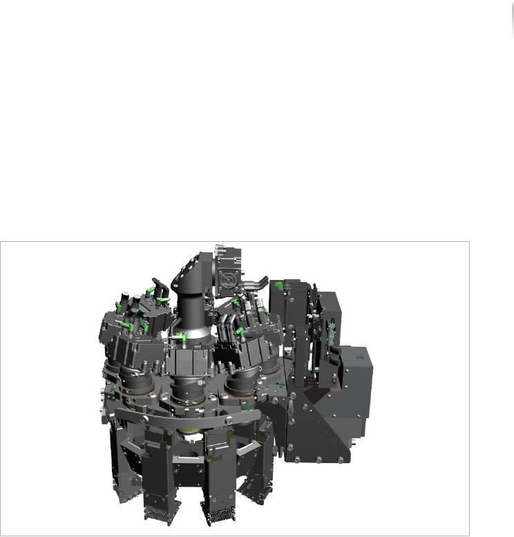
XM camera head
The XM camera head contains camera modules which generate the
image data and illumination modules which generate different illu-
mination types and directions. High power laser risk group 2 LEDs
are used for illumination. The optional fringe projector in 3D mode
allows to evaluate up to 8 image views from various angles, thus
performing 3D analyses in the entire field of view.
XM module
Orthogonal and AV (angled view) camera modules can be
combined into one XM camera head.
The following configurations of the XM module are possible:
XM4: 1 orthogonal camera and 4 angled cameras.
XM8: 1 orthogonal camera und 8 angled cameras.
Optional: XM 3D camera technology.
For additional information about technical specifications, variants
and combinations of camera modules, see „Technical specifica-
tions“ > „XM camera technology“ (Page 254).
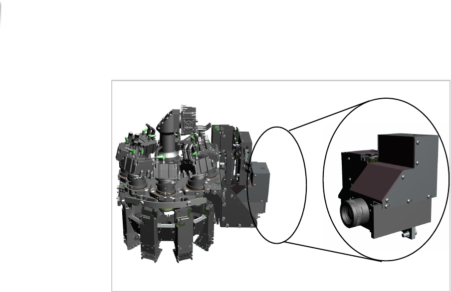
XM 3D camera technology
With the XM 3D camera technology, up to 8 image views from
various angles are evaluated and 3D analyses are realized in the
entire field of view.
To calculate the height information, a projector unit must be addi-
tionally integrated into the XM module. This digital projector unit
projects various fringe patterns which are simultaneously captured
by the angled cameras.
Product description
System components
42
Inspection system X7056 | Operating manual |
Version 3.1 Rev.006| 2016-01-06 | 30.009.1930a
XM sensor head with digital projector unit
For additional information about technical specifications, see
„Technical specifications“ > „XM camera technology“ (Page 254).
Flat panel detector (FPD)
The X-ray image acquisition is accomplished by the X-ray tube and
depending on the version, by one or five flat panel detectors. This
image acquisition is especially well-suited for X-ray analysis of
hidden components on the top side of the product before the
bottom side is assembled.
The flat panel detectors can be mounted in one of two different
ways:
Holder (Page 42)
Positioning unit (Page 43)
Holder
One flat panel detector is always located in the beam path beneath
the X-ray tube. If the system is equipped with 4 additional flat
panel detectors, they are arranged around the central image inten-
sifier.
Product description
System components
43
Inspection system X7056 | Operating manual |
Version 3.1 Rev.006| 2016-01-06 | 30.009.1930a
Holder
For additional information about technical specifications, see
„Technical specifications“ > „Flat panel detector“ (Page 256).
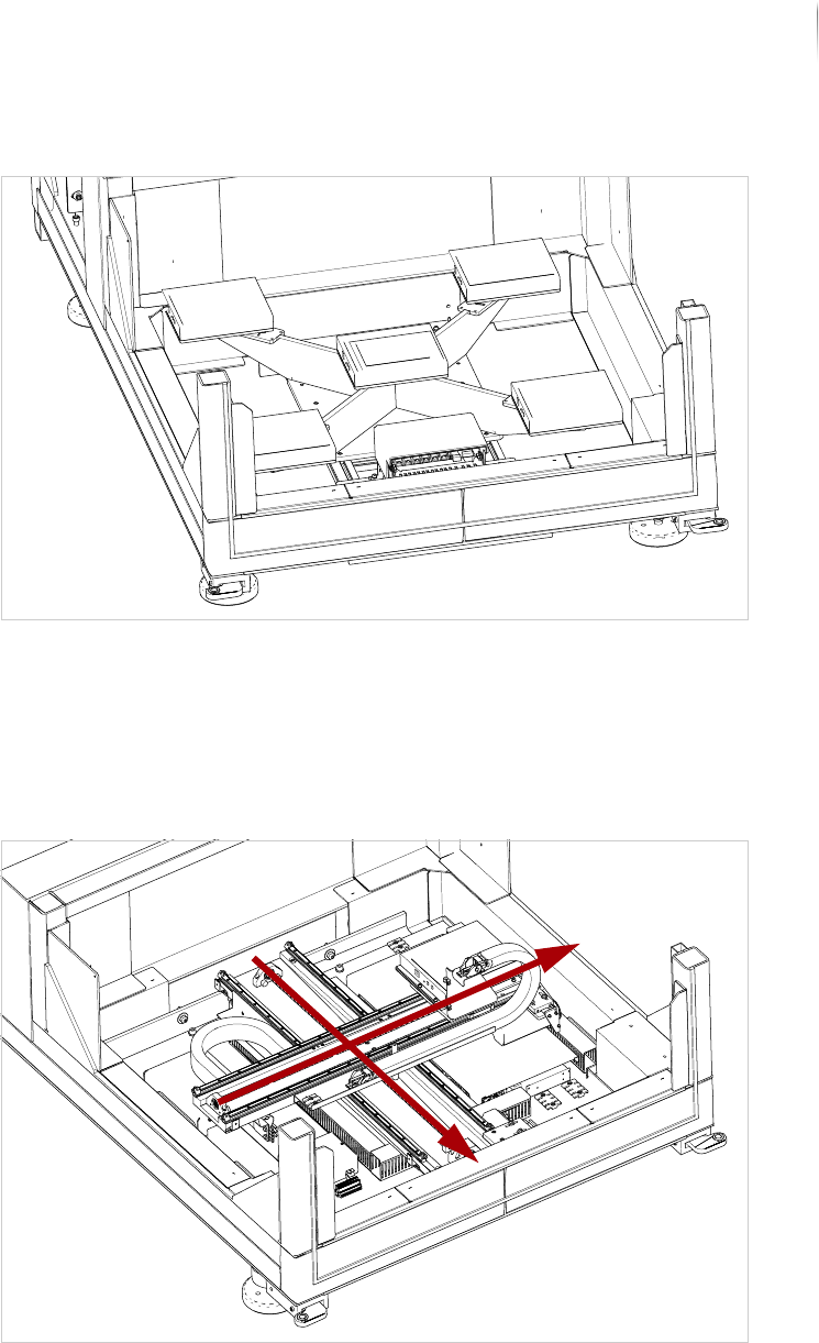
Positioning
unit
X-ray images are acquired through the X-ray tube and a flat panel
detector which can be moved in the x- and y-directions by its own
positioning unit.
Positioning unit
For additional information about technical specifications, see
„Technical specifications“ > „Flat panel detector“ (Page 256).
X
Y