X7056_Operating manual_en.pdf - 第26页
Product description The inspection sy stem 26 Inspection system X7056 | Operating manual | Version 3.1 Rev.006| 2016-01-06 | 30.009.1930a The inspection system The inspection system provides a ful ly automatic and simul …

Product description 25
Inspection system X7056 | Operating manual |
Version 3.1 Rev.006| 2016-01-06 | 30.009.1930a
Product description
This chapter presents the inspection system and its main compo-
nents.
It contains the following sections:
The inspection system (Page 26)
Options (Page 27)
Appropriate use (Page 28)
General view (Page 29)
Operation and display elements (Page 34)
System components (Page 37)
Energy supply and interfaces (Page 47)
Safety Features (Page 51)
Product description
The inspection system
26
Inspection system X7056 | Operating manual |
Version 3.1 Rev.006| 2016-01-06 | 30.009.1930a
The inspection system
The inspection system provides a fully automatic and simultaneous
optical (AOI) and X-ray (AXI) inspection of printed circuit boards.
Optical and X-ray inspection take place in two separated sections
within the system.
The inspection system fulfils all requirements for a fully protected
device according to German X-ray regulations from 4 October
2011 and US Standard 21 CFR§ 1020 - 40.
It provides reliable quality control at various production stages of
printed circuit boards. Inspection includes:
Assembly
Solder joints
Concealed defects on BGAs, µBGAs and CSPs
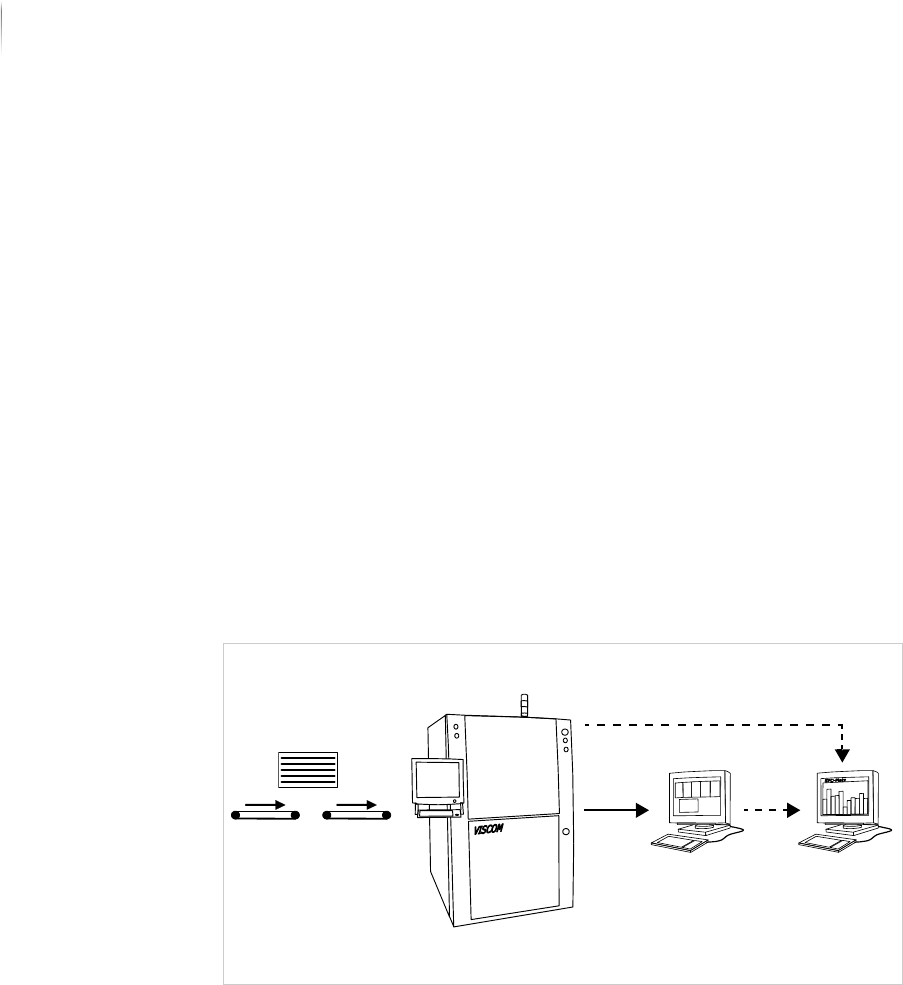
The inspection system is designed to be incorporated into a
production line. Electronics assemblies are conveyed to the inspec--
tion system by suitable conveyors.
Inspection system: integration into a production line
Confirmed defects can be transferred from the inspection system
to the verification station. There, the defects are classified and can
then be transferred to the SPC server for statistical evaluation.
If no verification station is used, the inspection results data can be
transferred directly to the SPC server. The SPC software analyzes
the measurement and results values of the Viscom inspection
systems.
Verification
station
SPC server
Inspection system

Product description
Options
27
Inspection system X7056 | Operating manual |
Version 3.1 Rev.006| 2016-01-06 | 30.009.1930a
Options
This section describes optional modules which are do not belong to
the standard delivery scope of the inspection system.
The following options are available:
Verification station (Page 27)
SPC server (Page 27)
Verification station
The verification station is connected to the inspection system
through a network. It displays defect images and classification
information, controls the verification station components and can
simultaneously evaluate inspection results that were transferred
from the inspection system to the verification station computer.
The inspection results are displayed on a monitor at the verifica--
tion station with indication of defect location and suggestions of
type of defect, and can be classified there. These results are
displayed on a monitor screen as individual defect images and
marked with reference to specific position on an overview image.
Confirmed defects can be transferred from the verification station
to the SPC server for statistical evaluation.
SPC server
For production process optimization, the inspection and classifica-
tion results are statistically processed and sorted according to
different criteria. The SPC software receives the processed data
from the inspection system, and displays deviation trends in paste
print, placement, soldering and bonding. In this way, prompt
corrections can be made to the production process.