X7056_Operating manual_en.pdf - 第111页
Software Viscom Vision Pi lot 111 Inspection system X7056 | Operating manual | Version 3.1 Rev.006| 2016-01-06 | 30.009.1930a System status information The S YSTEM STAT US INFORMAT ION window contains information about t…
Software
Viscom Vision Pilot
110
Inspection system X7056 | Operating manual |
Version 3.1 Rev.006| 2016-01-06 | 30.009.1930a
Viscom Vision Pilot
This section introduces the unified user interface for all Viscom
systems, the V
ISCOM VISION PILOT (VVP).
The following elements are described:
Start display (Page 110)
Log on window (Page 110)
System status information (Page 111)
Navigation (Page 112)
Start display
The log on window and the navigation buttons are on the start
display of the VVP.
Log on window
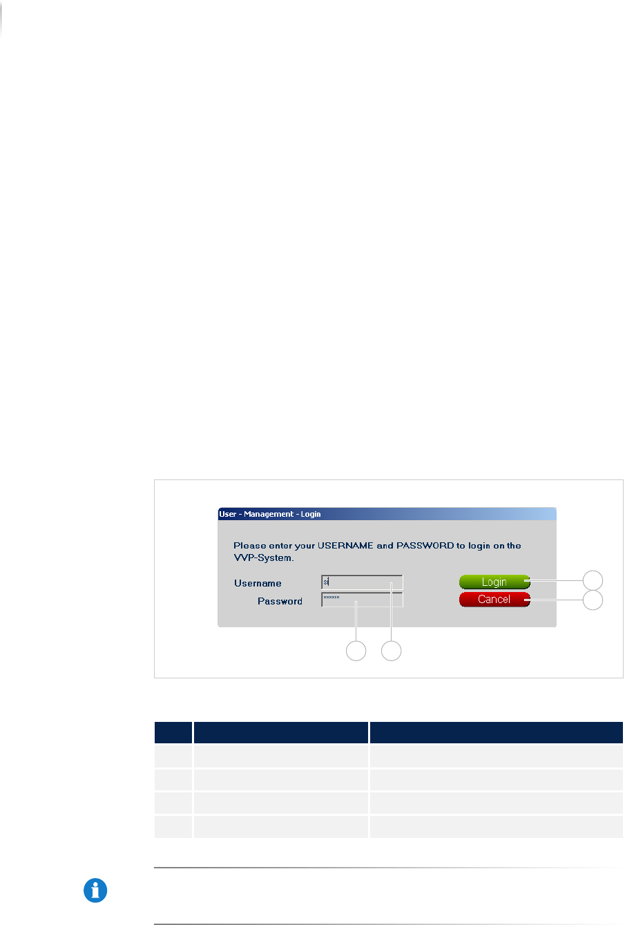
The log on window is used to register to the VVP.
Log on window VVP
NOTE
The user name name si and the password viscom are default
settings. These settings can be customized. Adapting the configu-
ration must be done by Viscom service personnel.
Description of the registration window
No. Name Description
1 LOG IN Registers the user.
2 CANCEL Closes the log on window.
3 USER NAME Entry of the user name.
4 PASSWORD Entry of the password.
1
2
34
Software
Viscom Vision Pilot
111
Inspection system X7056 | Operating manual |
Version 3.1 Rev.006| 2016-01-06 | 30.009.1930a
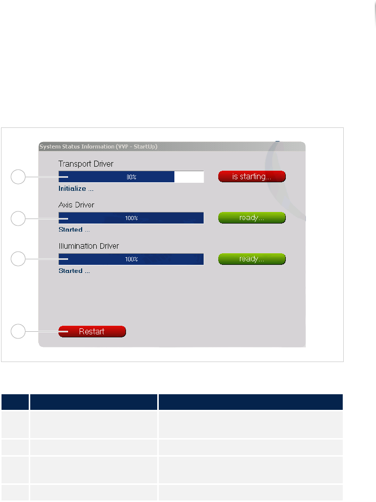
System status information
The SYSTEM STATUS INFORMATION window contains information about
the status of the transport, axes and illumination drivers.
SYSTEM STATUS INFORMATION window
Window description
No. Name Description
1 TRANSPORT Displays the progress of the transport
start.
2 AXES Displays the progress of the axes start.
3 ILLUMINATION Displays the progress of the illumina-
tion start.
4 RESTART Restarts the Viscom software.
1
2
3
4
Software
Viscom Vision Pilot
112
Inspection system X7056 | Operating manual |
Version 3.1 Rev.006| 2016-01-06 | 30.009.1930a
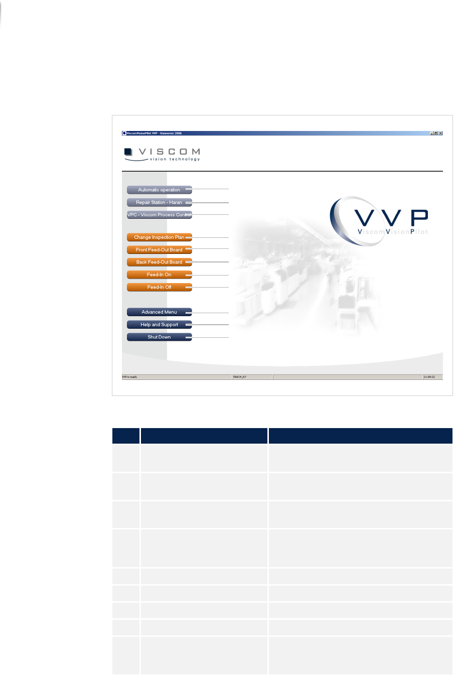
Navigation
The navigation buttons are explained in the following.
Unified user interface VVP
Description of the buttons
No. Name Description
1 AUTOMATIC OPERATION Starts the inspection in „Automatic
mode“ (Page 114).
2 REPAIR STATION -
HARAN (
OPTIONAL)
Starts the verification software.
3 VPC - VISCOM PROCESS
C
ONTROL (OPTIONAL)
Starts the SPC software.
4 CHANGE INSPECTION PLAN Opens the dialog window CHANGING
INSPECTION PLANS. See „Changing
inspection plans“ (Page 141)
5 FRONT FEED-OUT BOARD Outfeeds the PCB from the front track.
6 BACK FEED-OUT BOARD Outfeeds the PCB from the rear track.
7 FEED-IN ON Switches on the automatic PCB infeed.
8 FEED-IN OFF Switches off the automatic PCB infeed.
9 ADVANCED MENU Changes to the ADVANCED MENU of the
Viscom software. See „Advanced
menu“ (Page 142)
4
5
6
7
8
9
10
11
3
2
1