X7056_Operating manual_en.pdf - 第46页
Product description System componen ts 46 Inspection system X7056 | Operating manual | Version 3.1 Rev.006| 2016-01-06 | 30.009.1930a Shutter The shutter isolates the X-ray tube during operation wit h an open lift gate t…
Product description
System components
45
Inspection system X7056 | Operating manual |
Version 3.1 Rev.006| 2016-01-06 | 30.009.1930a
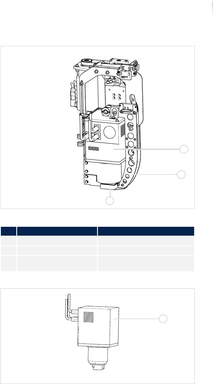
Sealed X-ray tube (assembled)
Sealed X-ray tube (dismounted)
Legend
No. Description Name
1 Sealed X-ray tube See „Sealed X-ray tube“ (Page 44)
2 Shutter See „Shutter“ (Page 46)
3 X-ray output window See „X-ray output window“ (Page
46)
1
2
3
4
Product description
System components
46
Inspection system X7056 | Operating manual |
Version 3.1 Rev.006| 2016-01-06 | 30.009.1930a
Shutter
The shutter isolates the X-ray tube during operation with an open
lift gate to prevent X-ray radiation leakage.
X-ray output
window
The X-rays are emitted from this window. It consists of beryllium.
After dismantling the tube a protective cover has to be attached to
this window in order to prevent contact with beryllium. The safety
instructions concerning the handling of beryllium must be
observed, see „Safety“ > „Chemical hazard“ (Page 23).
Battery
The sealed tube has a battery (Type CR2032). The software indi-
cates the time the battery must be replaced. To exchange the
battery, the X-ray tube must be dismounted. According to the
maintenance schedule, the battery has to be replaced every 3
years, see „Maintenance“ > „Exchanging the battery“ (Page 220)
Monitoring
the warning
lamp signals
The XLC assembly monitors the warning lamp signals and makes
sure that the functional warning lamp reports the failure of the
other lamps to the operator by blinking.
NOTICE
If one warning lamp fails, the radiation is switched off.
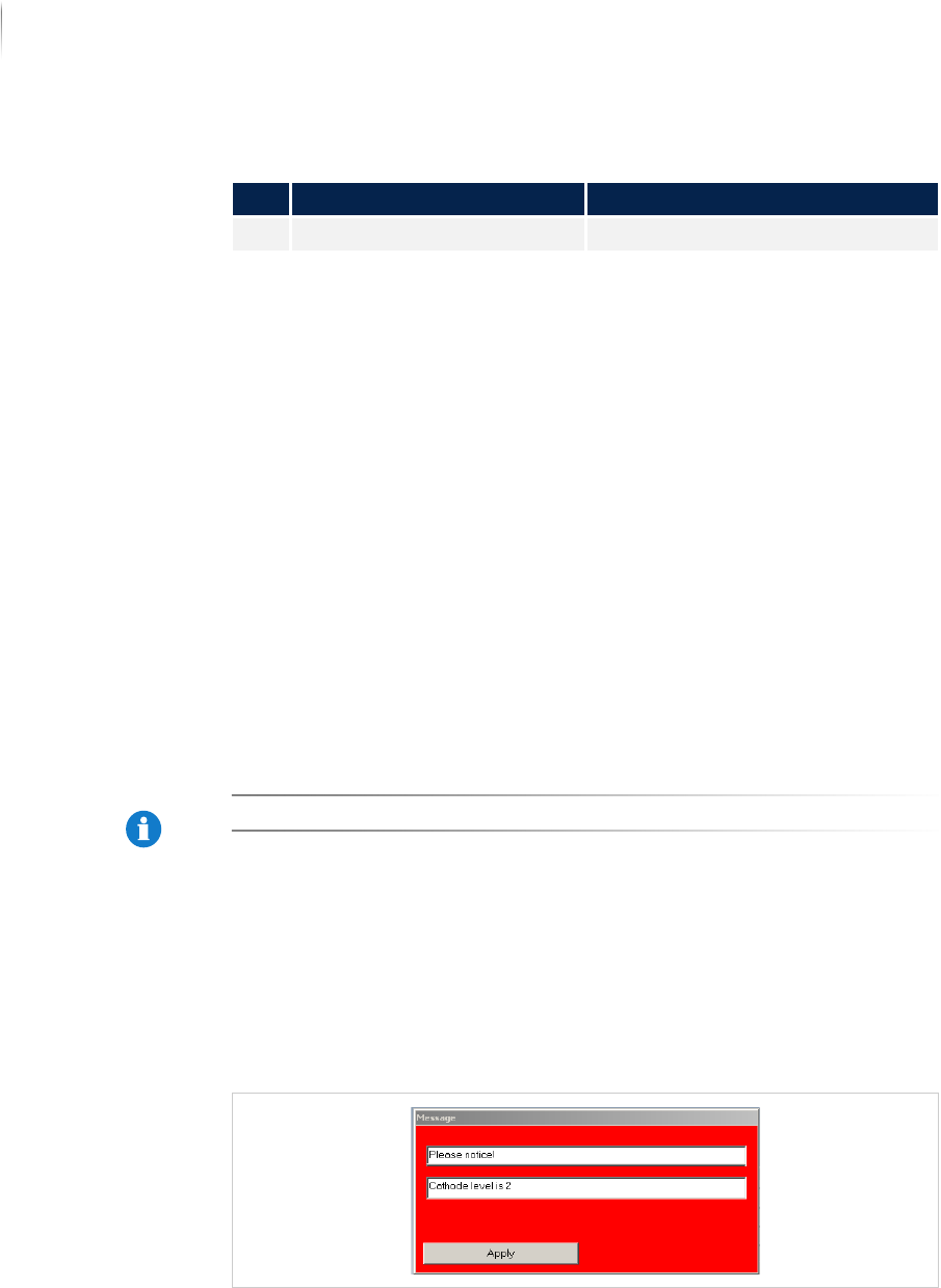
Life span
The driver of the sealed x-ray tube monitors a measurement
value, the cathode level, for display of the tube lifespan. There are
5 levels in all. If the current cathode level reaches value 1, a
warning mask with the text "Please note: Cathode level is 1" is
displayed. Then the tube is approaching the end of its lifespan, but
can still be used for about 1000 hours of irradiation time.
Mask: Cathode level
Viscom recommends planning installation of a replacement tube at
an early stage, to avoid unnecessary line downtime.
Legend
No. Name Description
4 Battery See „Battery“ (Page 46)

Product description
Energy supply and interfaces
47
Inspection system X7056 | Operating manual |
Version 3.1 Rev.006| 2016-01-06 | 30.009.1930a
Energy supply and interfaces
In this section, the position and type of the various inspection
system connections are described.
The following components are described:
Power supply (Page 47)
System computer (Page 47)
SMEMA and SV70 interface protocol (Page 47)
Interlock linkage (Page 49)
Power supply
Electrical supply is provided through a CEE plug connection for
three-phase connection (400 V), see .„Installation“ > „Electrical
installation“ (Page 78)
System computer
The system computers contain the connections for external and
internal peripheral devices. The correct connection of the system
computers can be taken form the current circuit plan.
SMEMA and SV70 interface protocol
Linking with the up- and downstream transport units is done
through a SMEMA or SV70 interface. For the interface connection
of the SMEMA-/SV70 interfaces, see „Installation“ > „Connecting
SMEMA/SV70“ (Page 88)
The following sections are covered:
Overview (Page 48)
SMEMA (Page 48)
SV70 (Page 48)
Configurable additional signals (Page 49)