X7056_Operating manual_en.pdf - 第242页
Packing Packing the in spection system 242 Inspection system X7056 | Operating manual | Version 3.1 Rev.006| 2016-01-06 | 30.009.1930a Securing the lift door Perform the following work steps: 1. Open the front lift door …
Packing
Packing the inspection system
241
Inspection system X7056 | Operating manual |
Version 3.1 Rev.006| 2016-01-06 | 30.009.1930a
Packing the inspection system
Always pack the inspection system for storage or transport. This
chapter describes how to pack the system.
It contains the following sections:
Preparing the wooden pallet (Page 241)
Securing the lift door (Page 242)
Setting the system feet (Page 242)
Fastening the inspection system (Page 243)
Wrapping the inspection system (Page 245)
Packing the inspection system in the transport case (Page 248)
Transporting the inspection system (Page 248)
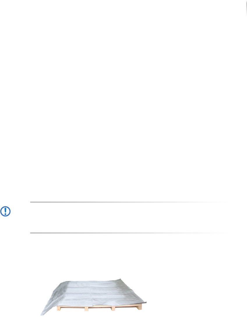
Preparing the wooden pallet
Required: Wooden pallet
Aluminum laminate sheet and bag
ATTENTION
Damage to the inspection system
There are power supply cables on the front and back sides of the
inspection system.
Make sure that no cables are underneath the system.
Perform the following work steps:
1. Lay out the aluminum laminate sheet on the wooden pallet with
the aluminum side down.
2. Set the inspection system carefully in the middle of the wooden
pallet.
The wooden pallet is prepared.
Packing
Packing the inspection system
242
Inspection system X7056 | Operating manual |
Version 3.1 Rev.006| 2016-01-06 | 30.009.1930a
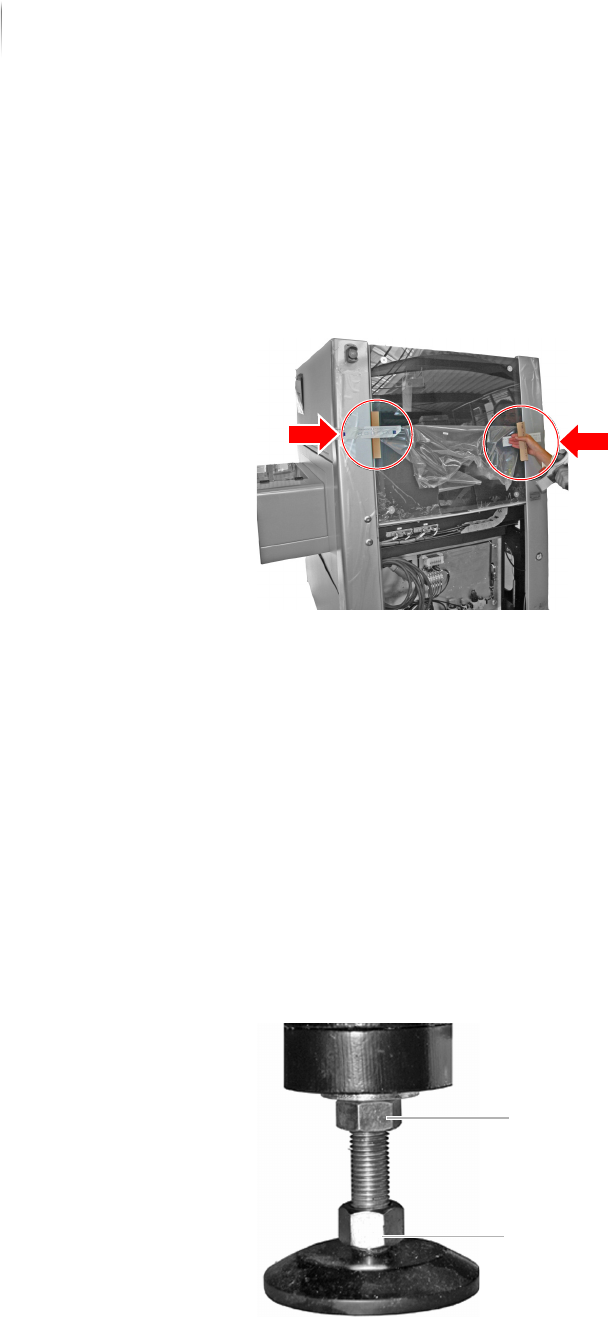
Securing the lift door
Perform the following work steps:
1. Open the front lift door.
2. Place two cardboard corners between the lift door and the
inspection system and fasten them with packing tape.
The lift door is secured.
Setting the system feet
To prevent damage to the system during transport, turn the
system feet out as far as they go.
Required: 30 mm open-end wrench
Carpenter's level
Perform the following work steps:
1. Loosen the lock nuts on the system feet.
The feet can now be turned in or out by their lower bolts.
2. Turn the system feet out to a height of 8 - 10 cm.
3. Check with a level to make sure the inspection system is hori-
zontally level.
Lock nut
Screw
Packing
Packing the inspection system
243
Inspection system X7056 | Operating manual |
Version 3.1 Rev.006| 2016-01-06 | 30.009.1930a
4. Set the inspection system in a horizontal position as indicated
by the level.
5. Tighten the lock nuts well to secure the system feet.
The system feet are set.
Fastening the inspection system
To prevent damage to the inspection system during transport,
fasten it to the wooden pallet. This chapter describes how to fasten
the inspection system, step by step.
This section covers the following themes:
Inspection system fastening points (Page 243)
Fastening the inspection system to the pallet (Page 244)
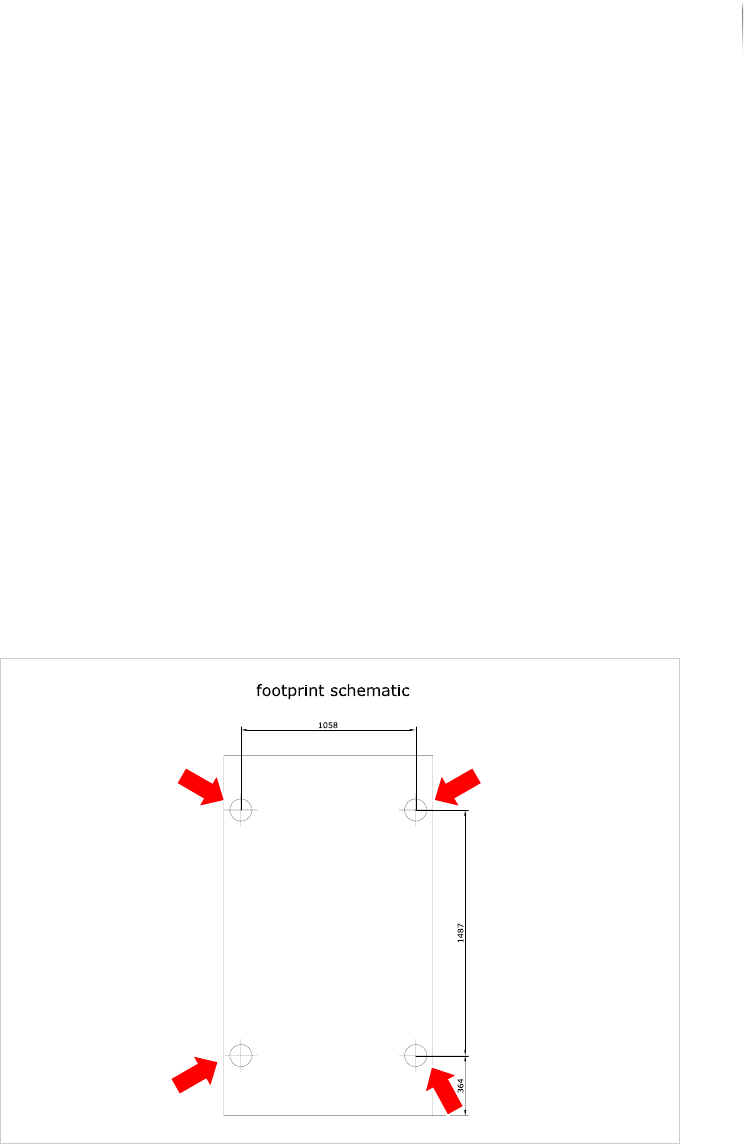
Inspection
system
fastening
points
The inspection system is fastened to the pallet at its outer four
feet. The following graphic shows the four fastening points:
Schematic diagram, system feet
Four transport clamps with two screws each are used to secure the
inspection system to the pallet.