X7056_Operating manual_en.pdf - 第71页
Installation Mechanical installation 71 Inspection system X7056 | Operating manual | Version 3.1 Rev.006| 2016-01-06 | 30.009.1930a Removing the transport locks from the AO I section The transport locks prevent movement …

Installation
Mechanical installation
70
Inspection system X7056 | Operating manual |
Version 3.1 Rev.006| 2016-01-06 | 30.009.1930a
Space
requirements
A minimum free space of 1 m on the sides of and behind the
inspection system is required for installation and maintenance
work.
Free space on the sides is not required, because the system is
integrated into a production line.
Setting the inspection system at its final usage site
This section describes how to set the inspection system. After they
are set, they can be installed..
The work steps in detail:
Transporting the inspection system to the usage site (Page 70)
Leveling the inspection system to the line (Page 70)
Transporting
the inspec-
tion system to
the usage site
Precondition: The setting conditions are met, see „Setting conditions“ (Page
69).
The industrial truck requirements are met, see„Delivery“ >
„Transport with industrial trucks“ (Page 57).
Perform the following work steps:
1. Position the industrial truck to the rear of the inspection
system.
2. Lift the inspection system carefully; pay attention to the
weight, the center of gravity and tipping angle.
3. Transport the inspection system to its final usage site.
The inspection system is at the final usage site.
Leveling the
inspection
system to the
line
Perform the following work steps:
1. Lower the inspection system carefully with the help of the
industrial truck.
2. When lowering the system, verify that the fixed front transport
side plate is in line with the production line.
The inspection system is levelled to the line.
Installation
Mechanical installation
71
Inspection system X7056 | Operating manual |
Version 3.1 Rev.006| 2016-01-06 | 30.009.1930a
Removing the transport locks from the AOI section
The transport locks prevent movement of the axes during trans-
port. Remove the transport locks before installation.
The following sections describe how to remove the transport
system locks:
Overview
Removing the transport locks
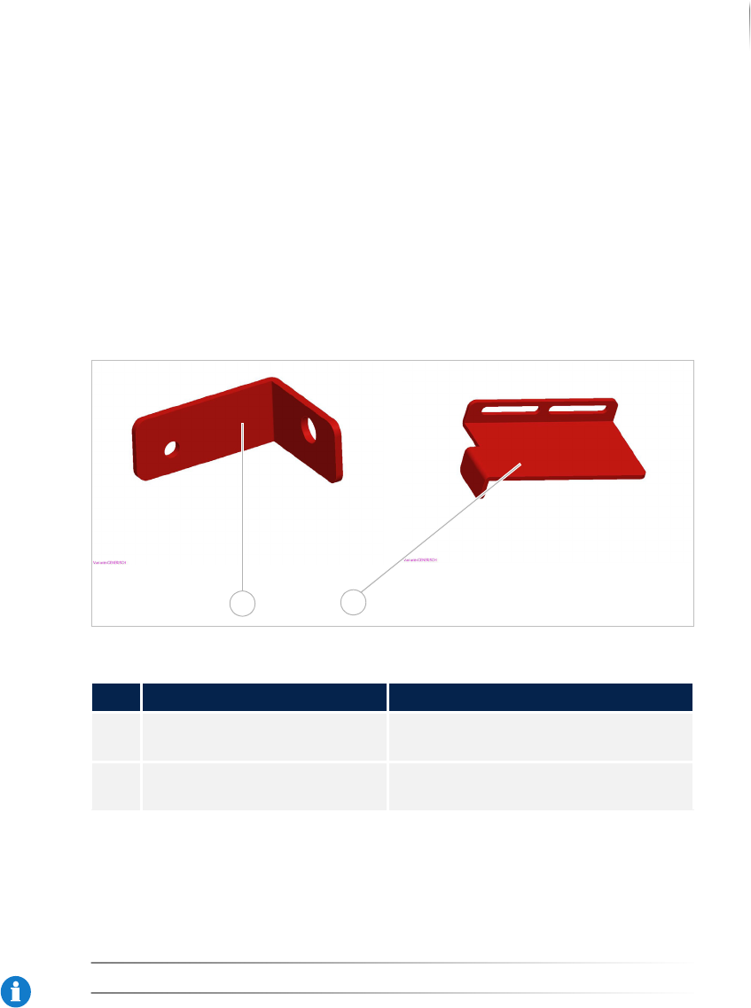
Overview
Transport locks AOI section
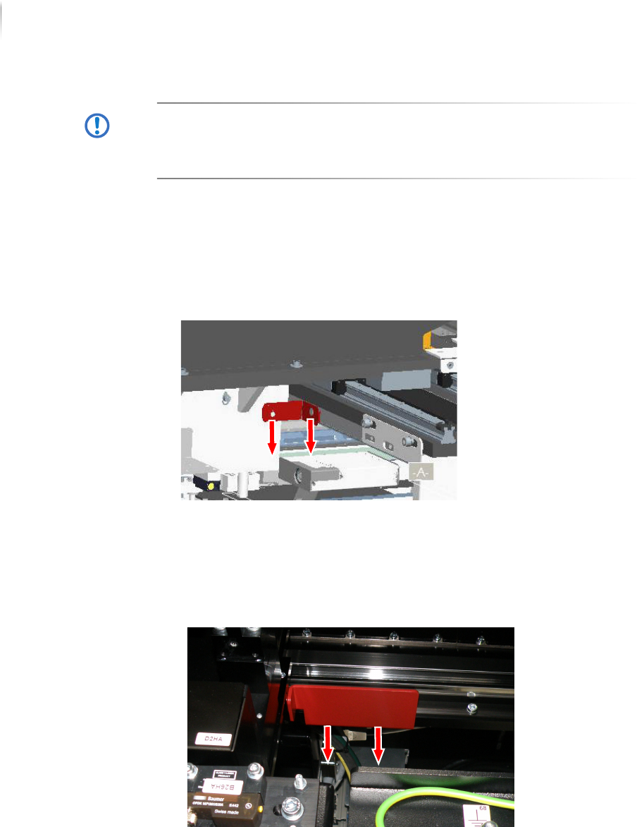
Removing the
transport
locks
Required:
Allen (hex) keys (5 and 6 mm)
NOTICE
Store the transport locks for later use.
Legend
No. Name Description
1 Upper transport lock, AOI
section
Secures the image acquisition unit.
2 Lower transport lock, AOI
section
Secures the AOI transport track.
1
2
Installation
Mechanical installation
72
Inspection system X7056 | Operating manual |
Version 3.1 Rev.006| 2016-01-06 | 30.009.1930a
ATTENTION
Damage to the inspection system
Unsecured transport axes may cause damage during transport.
Only remove the transport locks when the system is at its final
installation site.
Perform the following work steps:
1. Open the front lift door of the inspection system.
Access to the AOI section is open.
2. Remove the left screw of the upper transport lock (5 mm hex
key).
3. Remove the right screw of the upper transport lock (6 mm hex
key).
4. Remove the upper transport lock.
5. Remove the two screws from the lower transport lock (5 mm
hex key).
6. Remove the lower transport lock.
The AOI transport locks are removed.