X7056_Operating manual_en.pdf - 第93页
Installation First use 93 Inspection system X7056 | Operating manual | Version 3.1 Rev.006| 2016-01-06 | 30.009.1930a Checking the STOP mode Perform the following work steps: 1. Open the front lift door . The following…

Installation
First use
92
Inspection system X7056 | Operating manual |
Version 3.1 Rev.006| 2016-01-06 | 30.009.1930a
4. Turn on the UPS devices.
The system computers boot up.
5. Switch on the monitor.
The monitor displays the WindowsREGISTRATION WINDOW.
The inspection system is switched on.
Logging on
NOTICE
The user name si and the password viscom are default settings.
These settings can be customized. Adapting the configuration must
be done by Viscom service personnel.
Perform the following work steps:
1. Press the key combination
Ctrl+Alt+Delete.
The monitor displays the Windows Registration Window.
2. Enter the user name
si and the keyword viscom.
Log on is successful.
Checking the safety features
Make sure the safety features are working properly at first use and
each time the system is switched on.
The work steps in detail:
Checking the STOP mode (Page 93)
Checking EMERGENCY STOP (Page 93)
Checking the lift gate functioning (Page 94)
Checking the shutter functioning (Page 97)
Installation
First use
93
Inspection system X7056 | Operating manual |
Version 3.1 Rev.006| 2016-01-06 | 30.009.1930a
Checking the
STOP mode
Perform the following work steps:
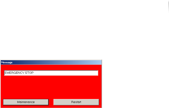
1. Open the front lift door.
The following message is displayed:
The STOP mode is actuated.
? The STOP mode does not actuate?
The safety circuit is defective.
Have the safety circuits checked by trained specialists or by
Viscom AG service technicians.
2. Close the front lift door.
3. Choose the R
ESTART button on the STOP notice.
The Viscom software is ended.
4. Start the Viscom software, see „Starting the Viscom software“
(Page 155).
The AOI software starts.
The AXI software starts.
5. Repeat steps 1 to 4 for the front door and the rear swing doors.
The STOP mode is checked.
Checking
EMERGENCY
STOP
Perform the following work steps:
1. Press the front EMERGENCY STOP button
The power to the inspection system is switched off.
The monitor is switched off.
The UPS ensures the regulated shutdown of the system
computer.
2. Turn the EMERGENCY STOP button clockwise to unlock it.
3. Press the ON button.
The ON button lights up.
? The white ON button does not light up?
The Interlock connection is faulty.
See „Checking the Interlock linkage“ (Page 100)
Installation
First use
94
Inspection system X7056 | Operating manual |
Version 3.1 Rev.006| 2016-01-06 | 30.009.1930a
4. If the UPS devices were manually switched off, switch them
back on.
The axes initialize.
The inspection system is ready to operate.
5. Start the Viscom software, see „Starting the Viscom software“
(Page 155).
The AOI software starts.
The AXI software starts.
6. Repeat steps 1 to 5 for the rear EMERGENCY STOP button.
The EMERGENCY STOP is checked.
Checking the
lift gate func-
tioning
Precondition: The inspection system is switched on.
The AXI transport track must be in the AXI section.
Perform the following work steps:
1. End the Viscom software, see „Ending the Viscom software“
(Page 158).
2. Actuate the STOP mode, see „Actuating the STOP mode“ (Page
149).
The lift gate is opened.
3. Cancel the STOP mode, see „Ending the STOP mode“ (Page
150).
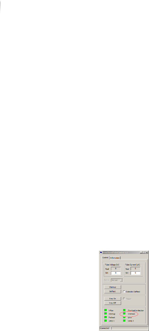
4. Under S
TART MENU > MAINTENANCE PROGRAM, select the program
X
RAYCLOSEDTUBECONTROL.
The start menu of the VXC software appears.
The Interlock connections are open.