X7056_Operating manual_en.pdf - 第153页
Operation Operating the safety feature s 153 Inspection system X7056 | Operating manual | Version 3.1 Rev.006| 2016-01-06 | 30.009.1930a Perform the following work steps: 1. Open the rear swing doors. The hand wheel fo…
Operation
Operating the safety features
152
Inspection system X7056 | Operating manual |
Version 3.1 Rev.006| 2016-01-06 | 30.009.1930a
WARNING
Hazard of injury
Burns caused by the motors for the PCB clamping.
When loosening the PCB clamping, use only the handwheel.
Perform the following work steps:
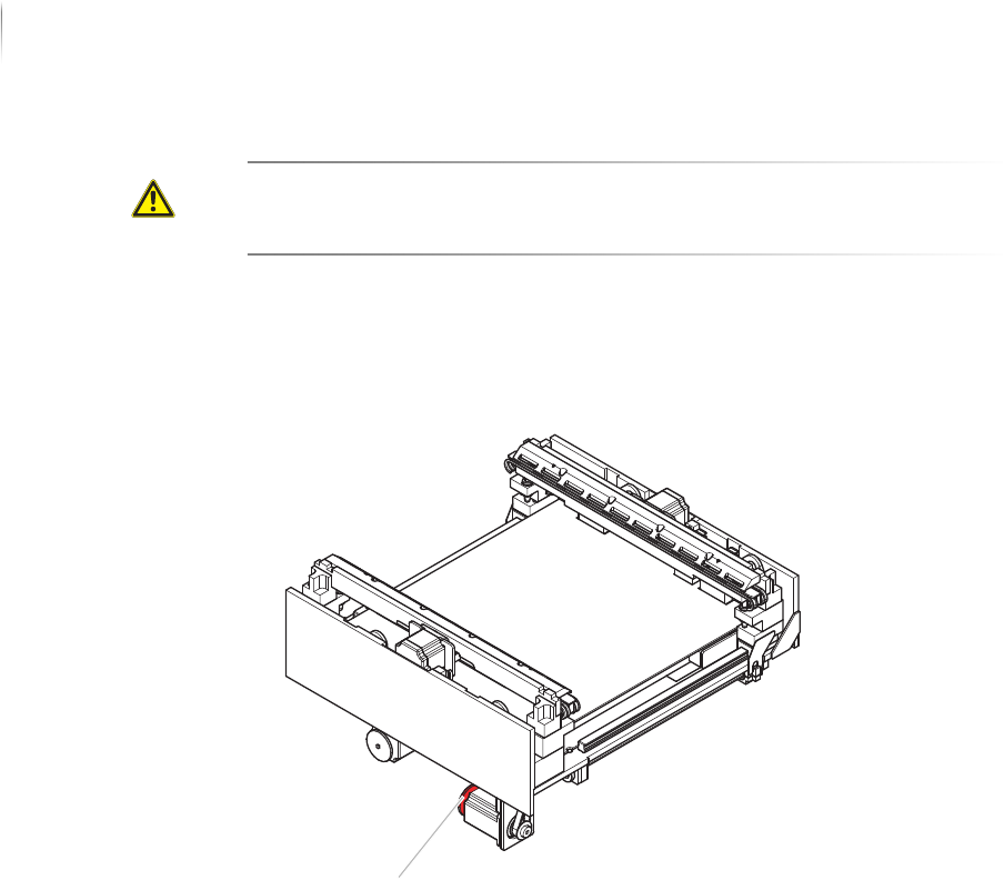
1. Open the front lift door.
The hand wheel for releasing the PCB clamping is below the
AOI transport track.
2. Push the transport track completely to the left to reach the
hand wheel.
3. Release the PCB clamping:
Turn the hand wheel clockwise to release the PCB clamping.
The PCB clamping is released.
Releasing the
PCB clamping
of the AXI
transport
track
To remove a PCB from the AOI or AXI transport during STOP or
EMERGENCY STOP states, release the clamping manually.
Precondition: The STOP mode is actuated.
Handwheel
Operation
Operating the safety features
153
Inspection system X7056 | Operating manual |
Version 3.1 Rev.006| 2016-01-06 | 30.009.1930a
Perform the following work steps:
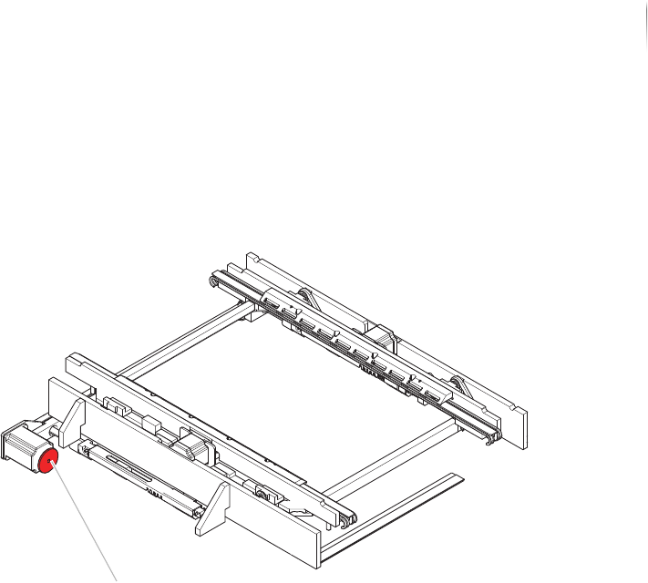
1. Open the rear swing doors.
The hand wheel for releasing the PCB clamping is below the AXI
transport track.
2. Pull the transport track AXI completely to the back.
3. Release the PCB clamping:
Turn the hand wheel clockwise to release the PCB clamping.
The PCB clamping is released.
Protective barrier safety features
The front swing and lift doors, the rear swing doors, the lift gate,
the shutter and the side panels are protective barrier safety
features of the inspection system. Opening any of the doors, the
lift gate or the shutter during operation actuates the STOP mode.
Handwheel

Operation
Switching on the inspection system
154
Inspection system X7056 | Operating manual |
Version 3.1 Rev.006| 2016-01-06 | 30.009.1930a
Switching on the inspection system
This section describes how to switch on the inspection system.
The work steps in detail:
Switching on the system (Page 154)
Registration (Page 154)
Switching on the system
Precondition: The inspection system is properly installed, see „Installation“
(Page 67).
The verification station computer is switched on and has booted
up.
The external in- and outfeed conveyors are switched on.
All of the system doors are closed.
Perform the following work steps:
1. Turn the main switch to
ON.
2. Press the white ON button.
The white ON button lights up.
The control elements are supplied with current.
3. Set the key switch to
ON.
4. Turn on the UPS devices.
The system computers boot up.
5. Switch on the monitor.
The monitor displays the WindowsREGISTRATION WINDOW.
The inspection system is switched on.
Registration
NOTE
The user name si and the password viscom are default settings.
These settings can be customized. Adapting the configuration must
be done by Viscom service personnel.
Perform the following work steps:
1. Press the key combination
Ctrl+Alt+Delete.
The monitor displays the Windows REGISTRATION WINDOW.
2. Enter the user name
si and the keyword viscom.
Log on is successful.