X7056_Operating manual_en.pdf - 第83页
Installation Integrating the i nspection system into the lin e 83 Inspection system X7056 | Operating manual | Version 3.1 Rev.006| 2016-01-06 | 30.009.1930a Line integrat ion: side view Line integrat ion: top view
Installation
Integrating the inspection system into the line
82
Inspection system X7056 | Operating manual |
Version 3.1 Rev.006| 2016-01-06 | 30.009.1930a
Integrating the inspection system into the
line
After the system is installed and then connected, integrate it into
the production line.
The work steps in detail:
Engineering Drawings (Page 82)
Adjusting the height of the inspection system (Page 84)
Leveling the inspection system to horizontal (Page 85)
Adjusting the transport track width (Page 86)
Checking the transport track width (Page 87)
Communication with adjacent devices (Page 87)
Network connection (Page 89)
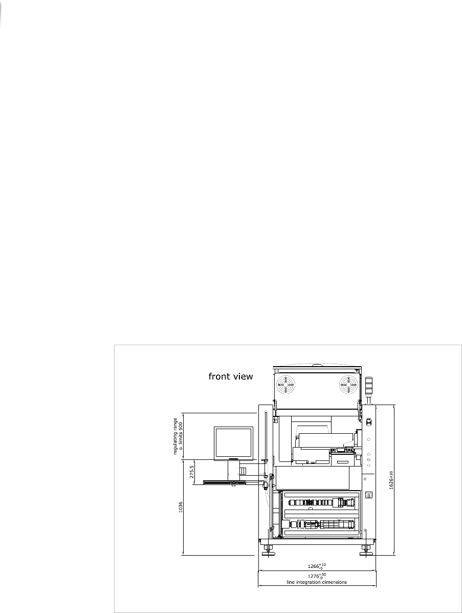
Engineering Drawings
The following drawings assist integration into the line.
Line integration: front view
Installation
Integrating the inspection system into the line
83
Inspection system X7056 | Operating manual |
Version 3.1 Rev.006| 2016-01-06 | 30.009.1930a
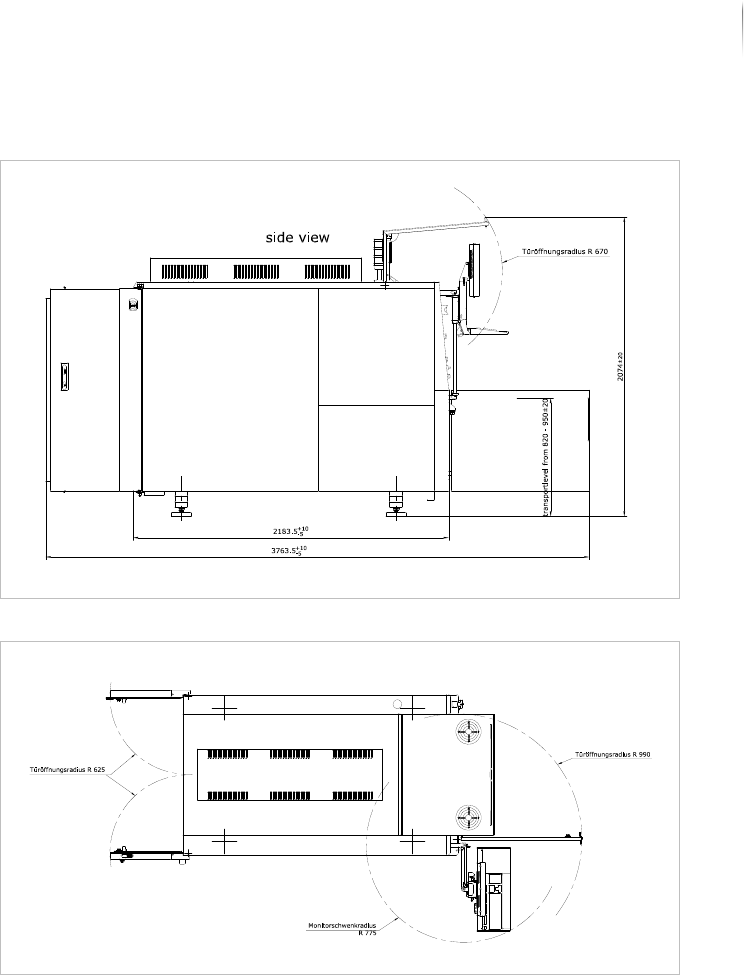
Line integration: side view
Line integration: top view
Installation
Integrating the inspection system into the line
84
Inspection system X7056 | Operating manual |
Version 3.1 Rev.006| 2016-01-06 | 30.009.1930a
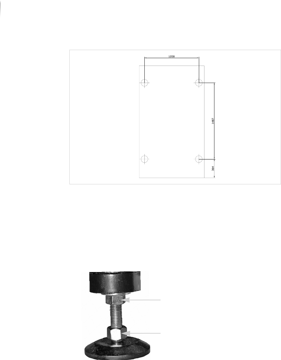
System feet
Adjusting the height of the inspection system
Required: 30 mm open-end wrench
Perform the following work steps:
1. Loosen the lock nuts on the system feet.
The feet can now be turned in or out by their lower bolts.
2. Place a PCB in the inspection system transport track.
3. Place the second PCB in the production line conveyor.
4. Slide the PCBs toward each other until they almost touch at the
transition between system and production line (see illustration).
The edges of the PCBs are parallel to each other.
Lock nut
Screw