1OM-1075-002.pdf - 第109页
AHB01EOPP 1.2.3 Preparation for Components and P .C.B.’ s • Preparation for Components The following is explained, presuming that the tape feeders are being used. As for the preparation for the vibratory stick feeders an…

AHB01EOPP
Operation Procedure
1. Confirm that the machine is set in the "STOP" mode.
2. Confirm that the front and rear safety doors are closed.
Confirm that the lamp of the [READY] button illuminates in green.
Otherwise, press the [READY] button and wait until the lamp illumi-
nates.
3. When the [ENABLE] button on the operation panel is pressed in 2
seconds after the [ALL] button (entitled "ZERO"), all devices except
"Conv. Wid. Adj. Axis" (one of the devices displayed in the "Origin
Information" group box of the "Origin/Signal Info." tab sheet) are ze-
roed.
Zeroing: The lamp of the [START] button illuminates.
Zeroing Completed: The lamp of the [START] button flick-
ers.
1.2 Preparation before Operation
0206-003 3 - 9
Note
AHB01EOPP
1.2.3 Preparation for Components and P.C.B.’s
• Preparation for Components
The following is explained, presuming that the tape feeders are
being used.
As for the preparation for the vibratory stick feeders and the
multi-layer tray feeders (option), refer to each instruction manual
for details.
(1) Press the [STOP] button.
(2) Detach the feeder base pullout prevention bar.
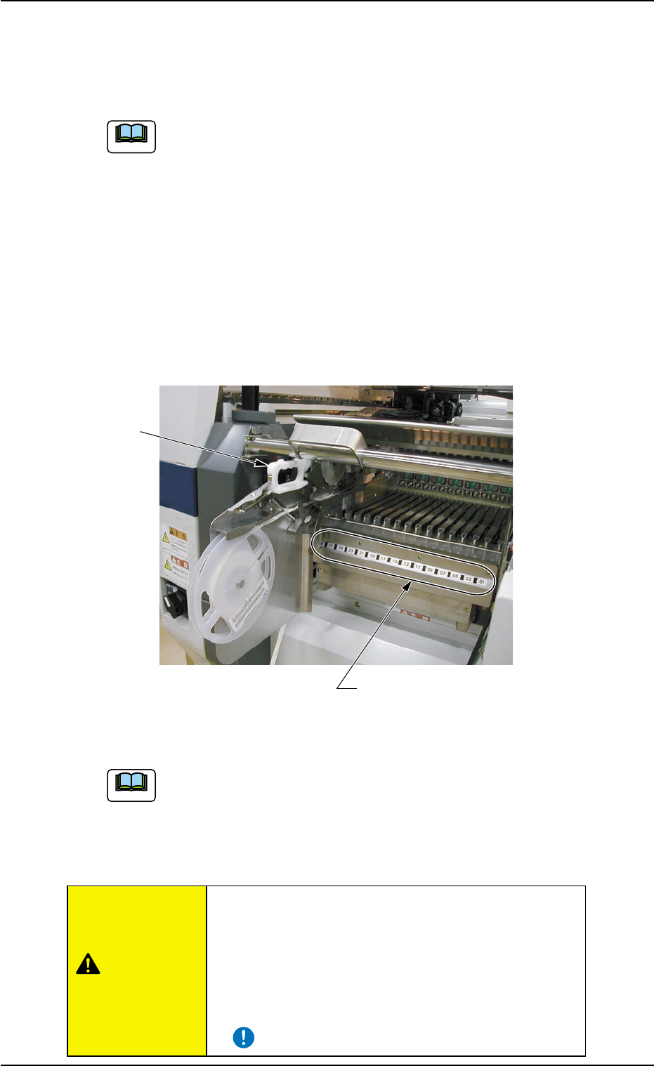
(3) Check which type of the tape feeder (grip color and type) should be
installed in which slot No. (Fdr. No.). After that, install the tape feed-
ers correctly.
Fig. 1C13
Refer to "Attachment and Detachment of Tape Feeders to Feeder
Base" in the instruction manual of tape feeders for details.
(4) Attach the feeder base pullout prevention bar.
• The feeders should be seated securely. Otherwise,
a collision with the head section or a pick-up error
will occur.
• Be sure to install the feeders on the correct feeder
slot Nos. (Fdr. No.). Otherwise, some components
may be trapped between the heads.
1.2 Preparation before Operation
0308-004 3-10
Fdr. No. Plate
Grip
Note
Note
CAUTION
AHB01EOPP
• Preparation for P.C.B.’s
In the case of normal automatic operation, confirm that P.C.B.’s are
prepared in the input machine.
When this machine is operated singly (actual placement test,
etc.), follow the steps below.
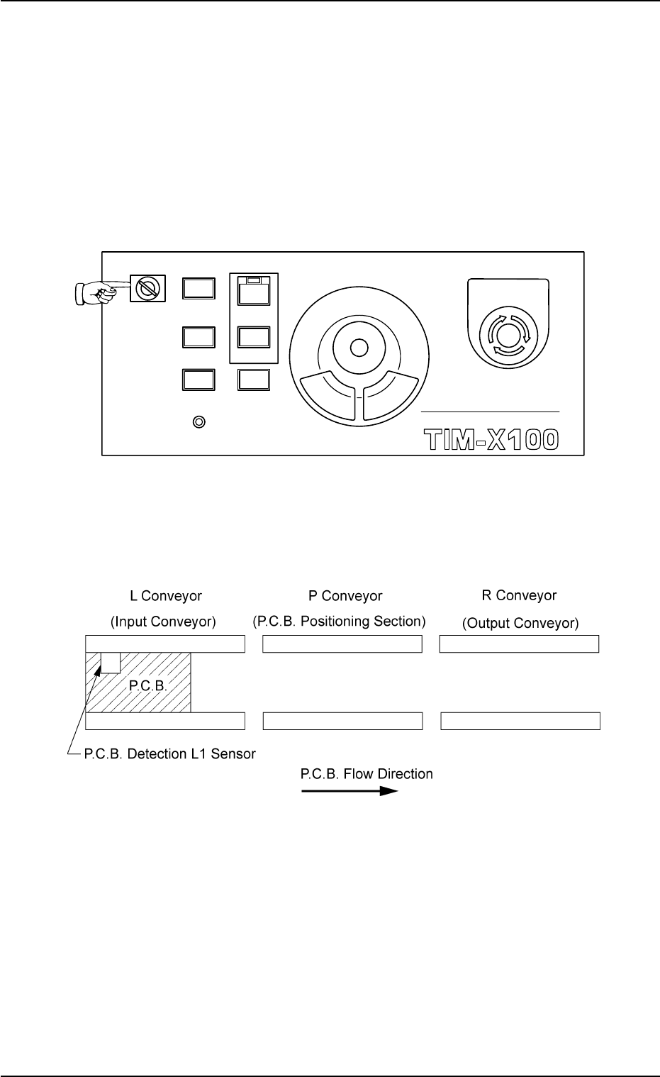
(1) Set the [OPERATION] switch to "SETUP" and open the safety
door.
Fig. 1C14
(2) Set a P.C.B. on the L conveyor (input conveyor) such that the
P.C.B. detection sensor is turned on (in red) as shown below.
Fig. 1C15 P.C.B. Flow Direction (Left Rear Reference): From Left to Right
0308-003 3-11
1.2 Preparation before Operation
MULTI FUNCTIONAL MOUNTER
STOP
LOCK
OPERATION
RUN SETUP
START
ENABLE
PNL CHANGE
READY
POWER ON
EMERGENCY