1OM-1075-002.pdf - 第52页
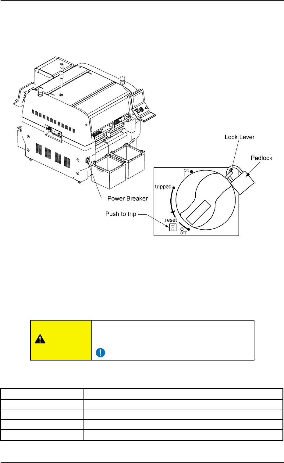
2 . 3 Equipment for Operations 2.3.1 Power Breaker Fig. 1A8 The power breaker is provided to supply or shut off power to the ma- chine. The power breaker can be locked with a padlock. Refer to "1.7.2 Locking the Pow…
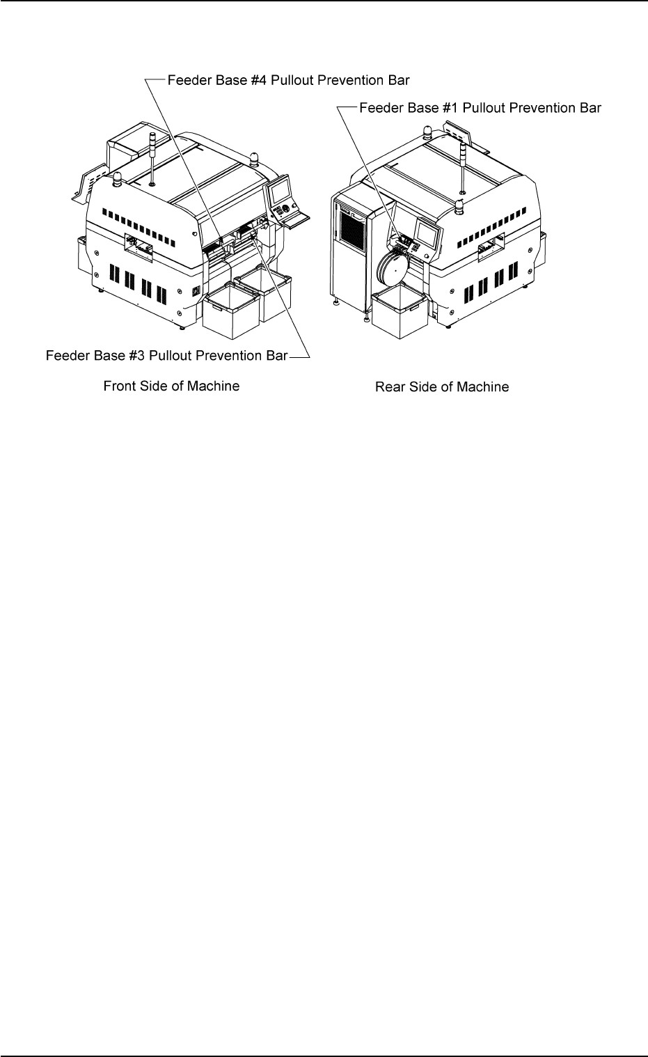
2.2.4 Feeder Base Pullout Prevention Bars
Fig. 1A7-1
These bars are used to prevent the operator from taking out any feeder
during operation, so that any collision between a head and a feeder can
be avoided. Each feeder base is provided with a bar.
The bar is automatically locked as soon as the machine starts running.
It is unlocked when the machine is stopped temporarily or completely.
No operation is available with the bar disengaged.
• Automatic Locking of Feeder Base Pullout Prevention Bar
The bar is automatically locked when the feeder base pullout preven-
tion bar is lifted and pushed and the machine starts running after it is
confirmed that the [READY] button is "ON" (Lamp: ON).
• Automatic Unlocking of Feeder Base Pullout Prevention Bar
The bar is automatically unlocked when the machine stopped tem-
porarily or completely, making it possible to pull and push down the
feeder base pullout prevention bar.
01 12-002 1-8
AHB01EOPP
2.2 Safety Devices
2.3 Equipment for Operations
2.3.1 Power Breaker
Fig. 1A8
The power breaker is provided to supply or shut off power to the ma-
chine.
The power breaker can be locked with a padlock.
Refer to "1.7.2 Locking the Power Breaker with the Padlock" in "Section
3 Scope of Automatic Operation" for the procedure to lock the breaker.
Before maintenance, etc., be sure to turn off the power
breaker and lock it with the padlock for safety purposes.
Table 1A1
Symbols/Names Functions
{ (OFF) Power OFF (Fig. 1A8)
tripped Power Interception due to Overcurrent
| (ON) Power Supply
Push to trip Test Button for Power Interception (caused by overcurrent)
2.3 Equipment for Operations
0308-004 1-9 AHB01EOPP
CAUTION
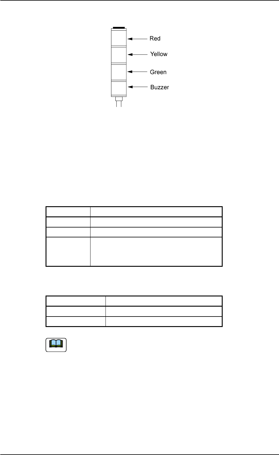
2.3.2 Light Tower
Fig. 1A9
The light tower indicates the condition of the machine with the lamps
and buzzer sounds.
Lamp Colors
The machine is factory-adjusted upon shipment.
Table 1A2
Lamp Colors Machine Condition
Red Error (Machine Stop)
Yellow Component Shortage (Warning)
Green Automatic Operation
Note: When the machine is in the standby
mode, this lamp flashes.
Buzzer
Table 1A2-1
Buzzer Machine Condition
Continuous Sound Emergency Stop
Intermittent Sound Error Occurrence
The condition of the machine corresponding to the parameters
specified for each lamp color can be changed at the "MACH
SETUP" window.
Refer to "2.3 "Configuration Setup" Tab" of "Section 5" in "Vol. 3:
Programming and Machine Data" for details.
0206-002 1-10 AHB01EOPP
2.3 Equipment for Operations
Note