1OM-1075-002.pdf - 第32页
T able 1X6 Switche Name Symbol Countermeasures [EMERGENCY STOP] Switch (1) (Rear Side) [EMERGENCY STOP] Switch (2) (Rear Side) [EMERGENCY STOP] Switch (3) (Front Side) [EMERGENCY STOP] Switch (4) (Front Side) When one of…
4. Safety-Related Features
4. Safety-Related Features
This session describes the safety switches and module protection sen-
sors.
4.1 Safety Switches
When an error is detected in the machine, the safety switches and sen-
sors are designed to stop the dangerous moving mechanisms of the
machine. Everything is processed on the machine side (hardware) with-
out using any software application on the computer side.
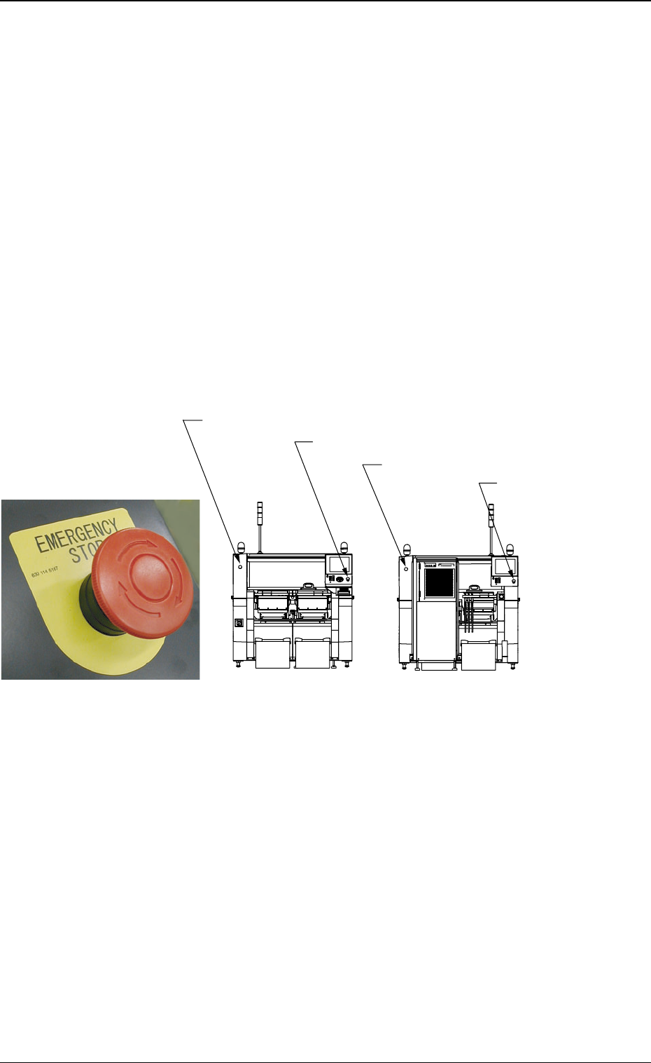
4.1.1 [EMERGENCY STOP] Switches
Press one of the [EMERGENCY STOP] switches to instantaneously
stop the machine in an emergency. Power is shut off and the machine
stops running.
0308-004 3 0 AHB01EOPP
Fig. 1X34
[EMERGENCY STOP] Switch
[EMERGENCY STOP]
Switch (1)
[EMERGENCY STOP] Switch (2)
[EMERGENCY STOP] Switch (4)
[EMERGENCY STOP] Switch (3)
Front Side of Machine
Rear Side of Machine
Fig. 1X35
Table 1X6
Switche Name Symbol Countermeasures
[EMERGENCY STOP]
Switch (1) (Rear Side)
[EMERGENCY STOP]
Switch (2) (Rear Side)
[EMERGENCY STOP]
Switch (3) (Front Side)
[EMERGENCY STOP]
Switch (4) (Front Side)
When one of the left switches is pressed, the follow-
ing measures are taken.
• The load power is shut off.
• Power to the motors excluding those for the
vacuum pump and the cooling fan is shut off.
Note: Power to the motors for the beam X/Y
axis, the traverse shaft and the elevator
shaft of the tray feeder is shut off in 1 sec-
ond after the [EMERGENCY STOP]
switch is pressed.
• 24 V load power in the solenoid valve system ex-
cluding the solenoid valves for component picks
and the control power sources such as those for
the sensors is shut off.
Note: The load power for the safety doors, the
solenoids for electromagnetic locks, and
the solenoid valve for tape feed is shut off
in 1 second after the [EMERGENCY
STOP] switch is pressed.
SPB31
SPB32
SPB33
SPB34
4.1 Safety Switches and Secsors
0308-004 3 1 AHB01EOPP
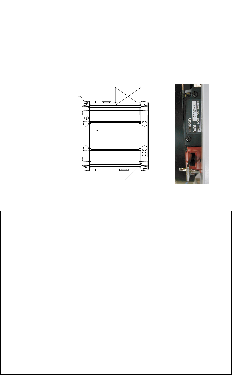
4.1.2 [Closed Safety Door Detection] Switches
When a safety door is opened with the [OPERATION] switch set to "RUN",
the corresponding [Closed Safety Door Detection] switch is activated,
causing an error and the load power is shut off.
When the [OPERATION] switch is set to "SETUP", only the power to
the motors for the X/Y beam and the heads is shut off.
The [Closed Safety Door Detection] switches are provided inside the
right edge of each safety door as follows.
Fig. 1X36
Switch Name Symbol Countermeasures
[Closed Safety Door
Detection A] Switch
(Rear Side)
[Closed Safety Door
Detection B] Switch
(Front Side)
0308-004 3 2 AHB01EOPP
Table 1X7
When either the front or the rear safety door is opened,
the following takes place.
• The load power is shut off.
• Power to the motors excluding those for the vacuum
pump and the cooling fan is shut off.
Note: Power to the motors for the beam X/Y axis,
the traverse shaft and the elevator shaft of
the tray feeder is shut off in 1 second after
the [EMERGENCY STOP] switch is
pressed.
• 24 V load power in the solenoid valve system ex-
cluding the solenoid valves for component picks
and the control power sources such as those for
the sensors is shut off.
Note: The load power for the safety doors, the so-
lenoids for electromagnetic locks, and the
solenoid valve for tape feed is shut off in 1
second after the [EMERGENCY STOP]
switch is pressed.
SQ1
SQ2
(Front Side of Machine)
(Rear Side of Machine)
[Closed Safety Door Detection B]
Switch
[Closed Safety Door Detection A]
Switch
4.1 Safety Switches and Secsors