1OM-1075-002.pdf - 第72页
2.4.2 Feeder Bases Fig. 1A20 The carriages carry feeders for component supply . Components are supplied from the tape or the vibratory stick feeders installed on the feeder bases. Each feeder base is provided with a &quo…
2.4 Main Units
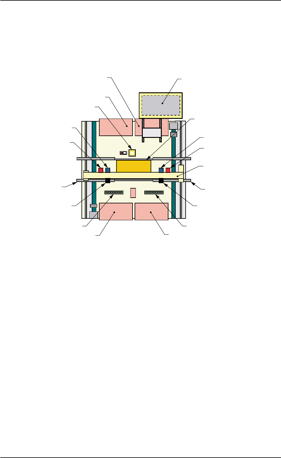
2.4.1 Location of Main Units
Fig. 1A18-2 Location of Main Units (Provided with Multi-Layer Tray Feeder #2)
2.4 Main Units
Front Side of Machine
Rear Side of Machine
Feeder Base #2
(Option)
Feeder Base #1
Fixed Camera A1
Head #2
P.E.C. Recognition
Camera 2
L Conveyor
Movable Camera 2
Nozzle Stocker B2
Feeder Base #4
Multi-Layer Tray Feeder #2
(Option)
P.C.B. Positioning Section
(P Conveyor)
Head #1
P.E.C. Recognition
Camera 1
X/Y Beam
R Conveyor
Movable Camera 1
Nozzle Stocker B1
Feeder Base #3
0206-003 1-25 AHB01EOPP
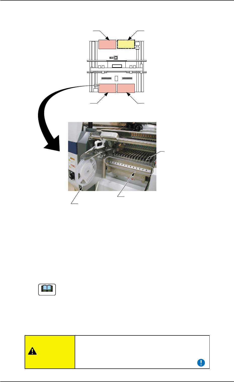
2.4.2 Feeder Bases
Fig. 1A20
The carriages carry feeders for component supply.
Components are supplied from the tape or the vibratory stick feeders
installed on the feeder bases.
Each feeder base is provided with a "Fdr. No." plate that indicates where
to allocate the feeders.
(a) Install the tape or the vibratory stick feeders (loaded with
components) on the corresponding feeder base.
Refer to the operation manual of the tape or the vibratory
stick feeder for details.
(b) The multi-layer tray feeder (option) or Feeder Base #2 (op-
tion) can be installed in the option space.
When a tape feeder is attached or detached, be sure
not to drop it.
Otherwise, an injury will result or the tape feeder
may be damaged.
Feeder Base
Fdr. No. Plate
Tape Feeder
Rear Side of Machine
Space for Option
Feeder Base #1
Front Side of Machine
Feeder Base #3
Feeder Base #4
(101 to 132)
(432 to 401)
(332 to 301)
(Top View)
(Rough View)
0308-004 1-26 AHB01EOPP
Note
2.4 Main Units
CAUTION
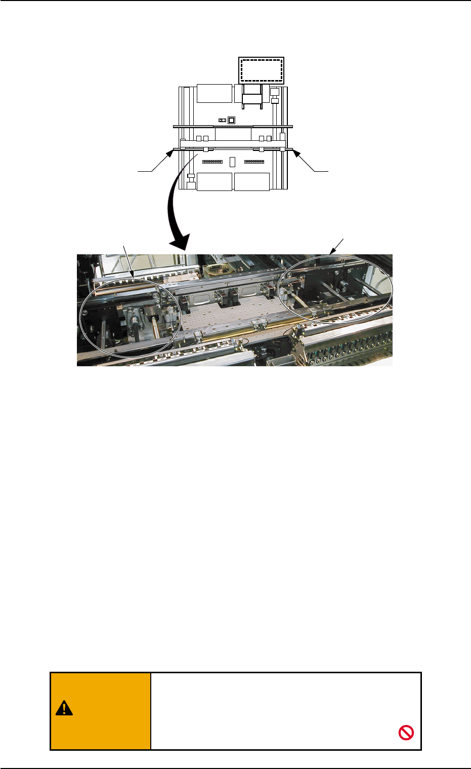
2.4.3 L and R Conveyor Sections
Fig. 1A22
These conveyors are used to receive a P.C.B. from the input machine
and transfer it to the place right before the P.C.B. positioning section or
carry the component-placed P.C.B. to the output machine.
When the P.C.B. flow direction is "L Æ R" (P.C.B. flow from left to right),
the L conveyor receives a P.C.B. from the input machine and transfers
it to the place right before the P.C.B. positioning section.
The R conveyor receives the component-placed P.C.B. from the P.C.B.
positioning section and transfers it to the output machine.
When the P.C.B. flow direction is "R Æ L" (P.C.B. flow from left to right),
the R conveyor receives a P.C.B. from the input machine and transfers
it to the place right before the P.C.B. positioning section.
The L conveyor receives the component-placed P.C.B. from the P.C.B.
positioning section and transfers it to the output machine.
Do not approach the machine closely if you wear
something that might be caught easily by the con-
veyors. Otherwise, an injury will result or the
machine will break down.
L Conveyor
L Conveyor
R Conveyor
R Conveyor
Rear Side of Machine
Front Side of Machine
(Top View)
(Rough View)
0308-003 1-27 AHB01EOPP
2.4 Main Units
WARNING