1OM-1075-002.pdf - 第35页
4.1.4 Maintenance Opening Detection Sensors Whenever a foreign object (hand, fingers, etc.) is detected between the safety door and a feeder during operation, these sensors are provided to stop the X/Y beam for safety pu…
4.1 Safety Switches and Secsors
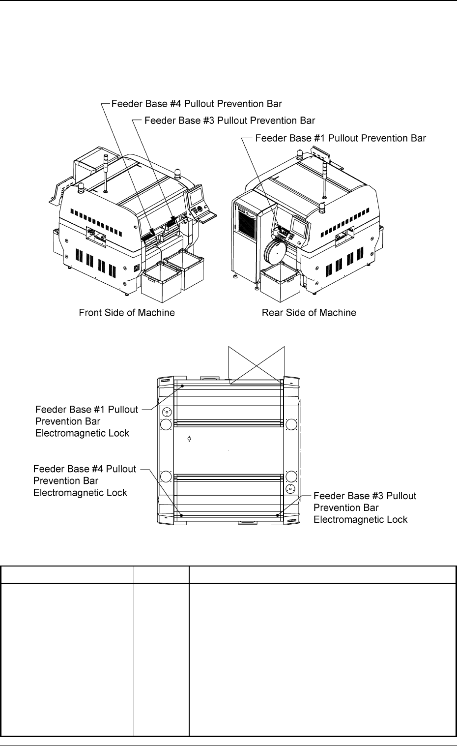
4.1.3 [Feeder Base Pullout Prevention Bar Lock Check] Switches
These switches are used to prevent any access to the spaces between
the feeders (the places where no feeders are installed) and any opera-
tor from taking out any installed feeder.
Fig. 1X37
Fig. 1X37-1
Switch Name Symbol Countermeasures
Feeder Base #1 Pullout
Prevention Bar Lock
Check
Feeder Base #3 Pullout
Prevention Bar Lock
Check
Feeder Base #4 Pullout
Prevention Bar Lock
Check
0206-003 3 3
AHB01EOPP
Table 1X8
• While the machine is running, these bars are locked
and will not open.
SQ03
SQ04
SQ05
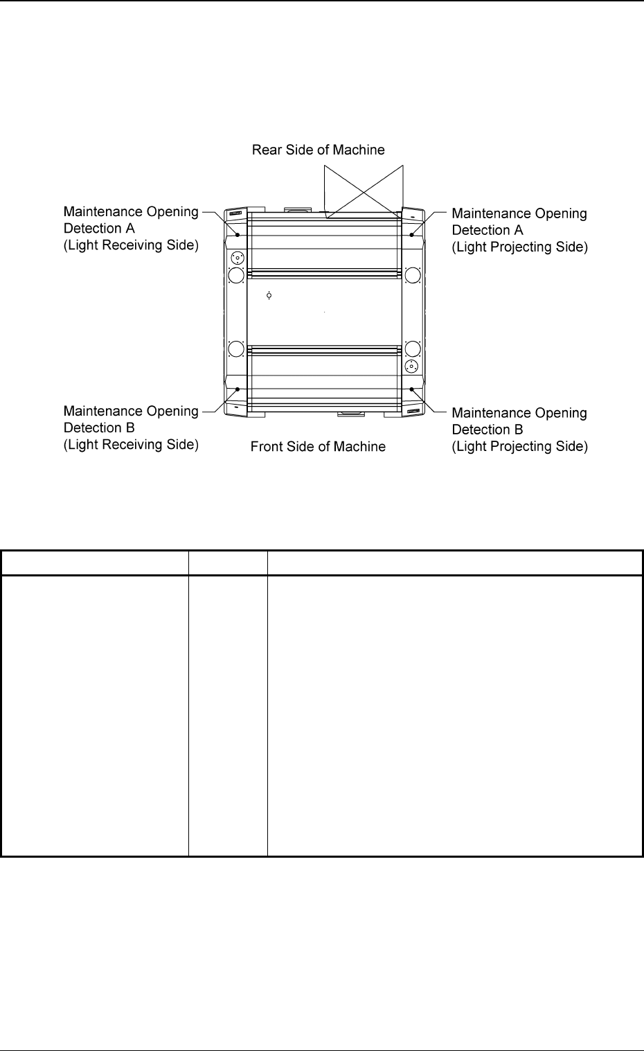
4.1.4 Maintenance Opening Detection Sensors
Whenever a foreign object (hand, fingers, etc.) is detected between the
safety door and a feeder during operation, these sensors are provided
to stop the X/Y beam for safety purposes.
Fig. 1X38 Top View of Machine
Switch Name Symbol Countermeasures
Maintenance Opening
Detection A
(Light Projecting Side)
Maintenance Opening
Detection A
(Light Receiving Side)
Maintenance Opening
Detection B
(Light Projecting Side)
Maintenance Opening
Detection B
(Light Receiving Side)
Table 1X9
When one of these sensors is turned OFF (light emit-
ted and received), the following measures are taken.
• The excitations of the beam X/Y axis and the nozzle
U/D axis are shut off.
(At the same time, the nozzle U/D axis is braked.)
BPH082AT
BPH082AR
BPH082BT
BPH082BR
0206-003 3 4 AHB01EOPP
4.1 Safety Switches and Secsors
4.2 Module Protection Sensors
0206-003 3 5 AHB01EOPP
4.2 Module Protection Sensors
This session describes the main sensors that are provided for ma-
chine protection.
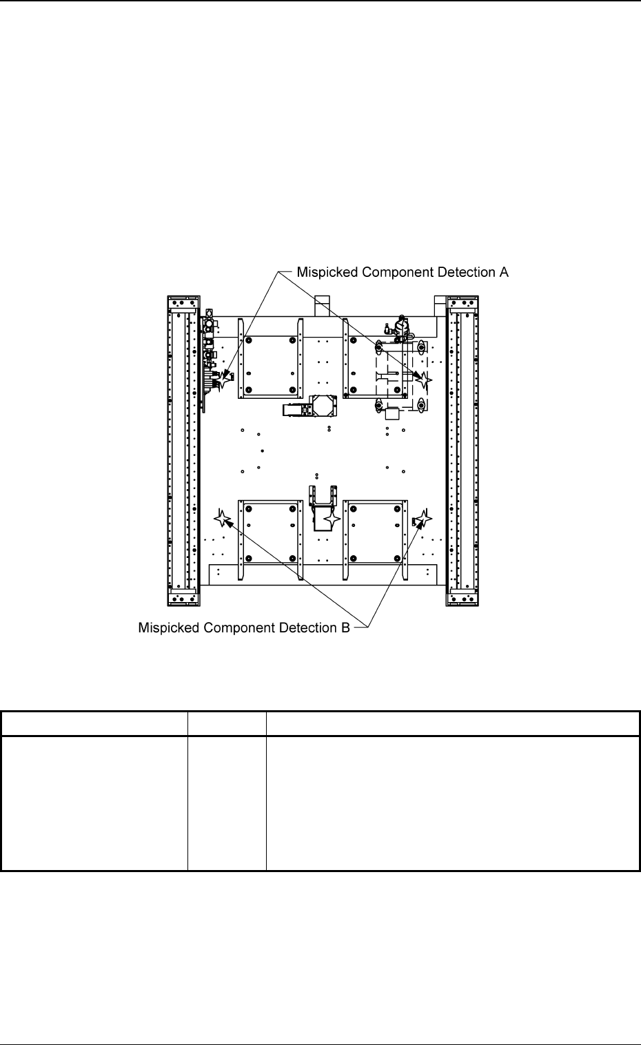
4.2.1 Mispicked Component Detection Sensors
These sensors are provided to detect mispicked components, etc., at
the component pick-up position for the protective purposes of the ma-
chine.
Fig. 1X39 Sectional View of Machine
Sensor Name Symbol Countermeasures
Mispicked Component
Detection A
(Rear Side)
Mispicked Component
Detection B
(Front Side)
Table 1X10
• The excitations of the beam X/Y axis, the nozzle U/D
axis, and the head rotational axis are shut off. (At the
same time, the nozzle U/D axis is braked.)
• The nozzle change axis stops rapidly after the sen-
sor has detected a mispicked component.
BPH071
BPH072