1OM-1075-002.pdf - 第36页
4.2 Module Protection Sensors 0206-003 3 5 AHB01EOPP 4. 2 Module Protection Sensors This session describes the main sensors that are provided for ma- chine protection. 4.2.1 Mispicked Component Detection Sensors These se…
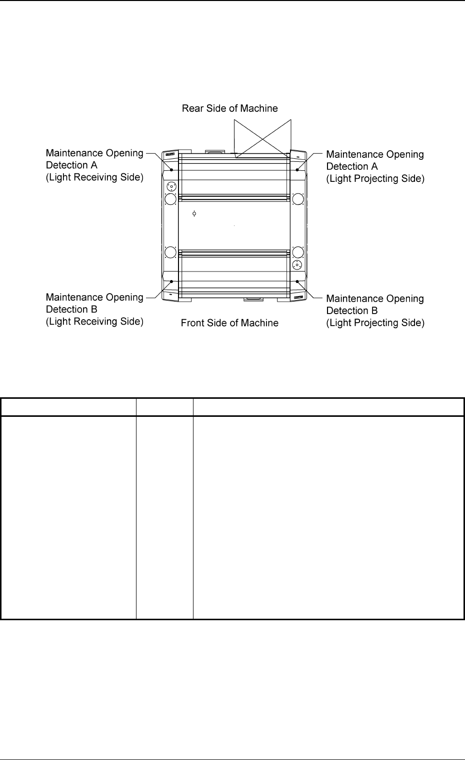
4.1.4 Maintenance Opening Detection Sensors
Whenever a foreign object (hand, fingers, etc.) is detected between the
safety door and a feeder during operation, these sensors are provided
to stop the X/Y beam for safety purposes.
Fig. 1X38 Top View of Machine
Switch Name Symbol Countermeasures
Maintenance Opening
Detection A
(Light Projecting Side)
Maintenance Opening
Detection A
(Light Receiving Side)
Maintenance Opening
Detection B
(Light Projecting Side)
Maintenance Opening
Detection B
(Light Receiving Side)
Table 1X9
When one of these sensors is turned OFF (light emit-
ted and received), the following measures are taken.
• The excitations of the beam X/Y axis and the nozzle
U/D axis are shut off.
(At the same time, the nozzle U/D axis is braked.)
BPH082AT
BPH082AR
BPH082BT
BPH082BR
0206-003 3 4 AHB01EOPP
4.1 Safety Switches and Secsors
4.2 Module Protection Sensors
0206-003 3 5 AHB01EOPP
4.2 Module Protection Sensors
This session describes the main sensors that are provided for ma-
chine protection.
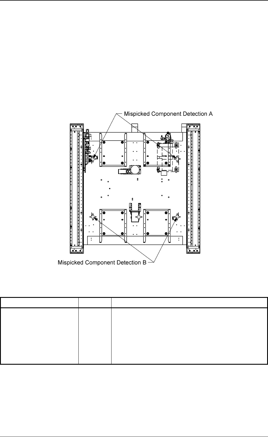
4.2.1 Mispicked Component Detection Sensors
These sensors are provided to detect mispicked components, etc., at
the component pick-up position for the protective purposes of the ma-
chine.
Fig. 1X39 Sectional View of Machine
Sensor Name Symbol Countermeasures
Mispicked Component
Detection A
(Rear Side)
Mispicked Component
Detection B
(Front Side)
Table 1X10
• The excitations of the beam X/Y axis, the nozzle U/D
axis, and the head rotational axis are shut off. (At the
same time, the nozzle U/D axis is braked.)
• The nozzle change axis stops rapidly after the sen-
sor has detected a mispicked component.
BPH071
BPH072
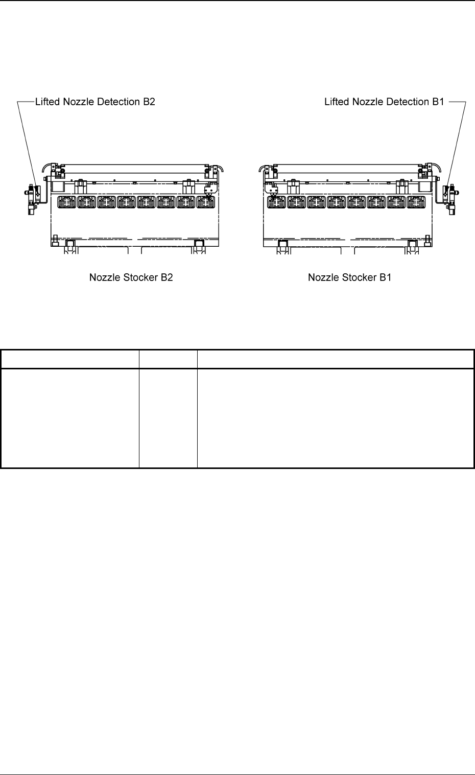
4.2.2 Lifted Nozzle Detection Sensors
These sensors are provided to protect the placement heads when a
vacuum nozzle is ejected out of the nozzle stocker.
Fig. 1X40 Front View of Machine
Sensor Name Symbol Countermeasures
Lifted Nozzle Detection B1
Lifted Nozzle Detection B2
Table 1X11
When one of these sensors is turned OFF (light emit-
ted and not received), the following measures are taken.
• The excitations of the beam X/Y axis and the nozzle
U/D axis are shut off.
(At the same time, the nozzle U/D axis is braked.)
BPH061
BPH061
0206-003 3 6
AHB01EOPP
4.2 Module Protection Sensors