1OM-1075-002.pdf - 第56页
2.3.5 [TRA Y LOAD] Switch (Option) Fig. 1A10-2 The [TRA Y LOAD] switch (green lamp) is used to indicate how the multi- layer tray feeder (option) is replenished with component supply . Lamp ON/OFF Condition T able 1A2-3 …
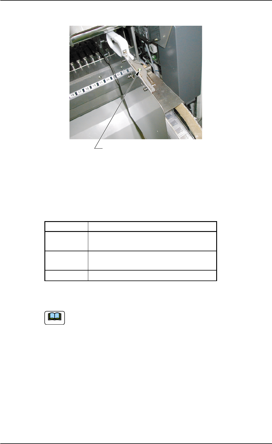
2.3.4 Status Indicator
Fig. 1A10-1
The status indicator (green lamp) is used to indicate how the tape feed-
ers are replenished with component supply.
Lamp ON/OFF Condition
Table 1A2-2
Mode Condition of Feeder Base
ON Loaded with Components
(Replenishment Completed)
ON and OFF Not Loaded with Components
(Component Shortage)
OFF Not used in the current pattern program
When the status indicator flickers, replenish the component supply.
(a) Refer to "1.4.1 Replenishment of Components" in "Sec-
tion 3" for the detailed information on the replenishment of
components.
(b) The status indicator flickers (indicating component short-
age) according to the parameter specified in the "1" text
box of the label "Error process" in the component library
data.
0206-001 1-1 1-1
AHB01EOPP
Status Indicator
2.3 Equipment for Operations
Note
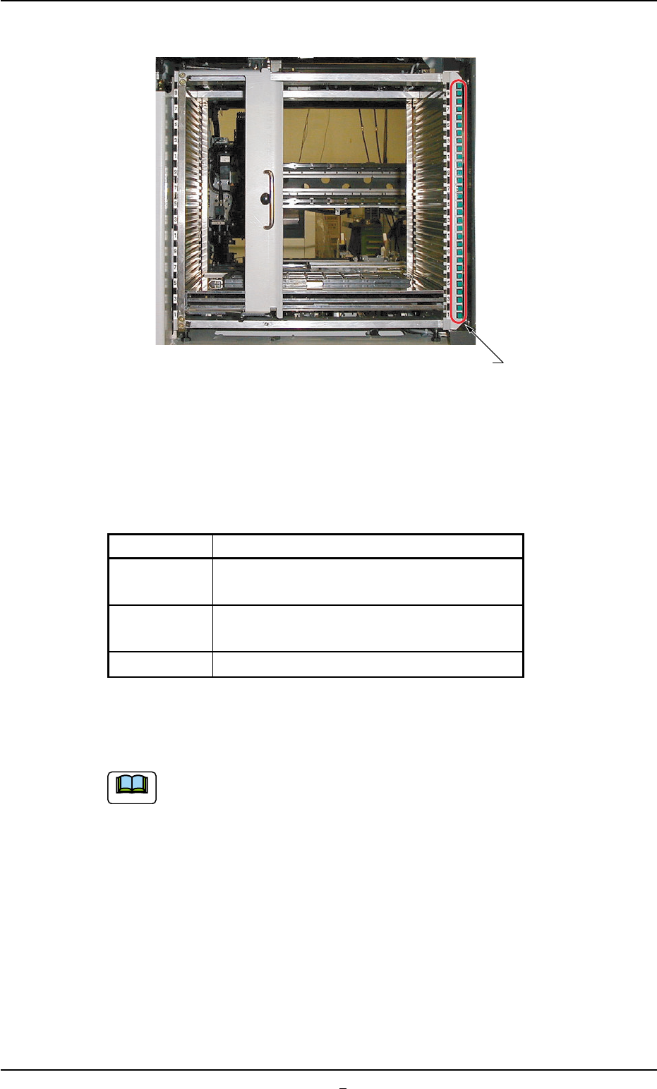
2.3.5 [TRAY LOAD] Switch (Option)
Fig. 1A10-2
The [TRAY LOAD] switch (green lamp) is used to indicate how the multi-
layer tray feeder (option) is replenished with component supply.
Lamp ON/OFF Condition
Table 1A2-3
Mode Condition of Multi-Layer Tray Feeder
ON Loaded with Components
(Replenishment Completed)
ON and OFF Not Loaded with Components
(Component Shortage)
OFF Not used in the current pattern program
When the [TRAY LOAD] switch flickers, replenish the component sup-
ply.
(a) Refer to the instruction manual "Multi-Layer Tray Feeder
(TIM-X Series)" for the replenishment of tray components.
(b) The [TRAY LOAD] switch flickers (indicating component
shortage) according to the parameters specified in the
"Matrix X" and "Matrix Y" text boxes of the label "Tray data"
or the "1" text box of the label "Error process" in the com-
ponent library data.
2.3 Equipment for Operations
0308-002 1-1 1-2 AHB01EOPP
[TRAY LOAD] Switch
Note
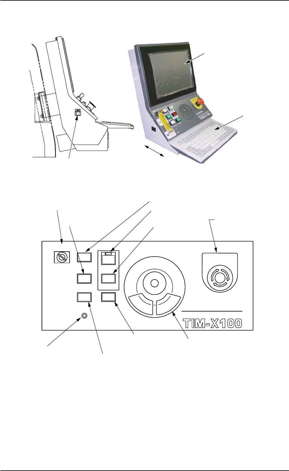
2.3.6 Front Operation Panel
Fig. 1A11
Fig. 1A12
Arranged on the operation panels are switches and buttons required to
operate the machine.
The machine is provided with the front and rear operation panels and
can be operated from either one of the panels. Panel selection is pos-
sible with the [PNL CHANGE] buttons.
A slide-type keyboard is stored under the front operation panel.
*12 Front Touch Screen
*10 Keyboard
0308-004 1-12 AHB01EOPP
*13 Working Lamp Switch
MULTI FUNCTIONAL MOUNTER
STOP
LOCK
OPERATION
RUN SETUP
START
ENABLE
PNL CHANGE
READY
POWER ON
EMERGENCY
*8 [OPERATION] Switch
*7 [READY] Button
*1 [POWER ON] Button
*4 [ENABLE] Button
*2 [START] Button
*9 [EMERGENCY
STOP] Switch
*6 [LOCK] Lamp
*5 [PNL CHANGE] Button
*3 [STOP] Button
*11 Pointing Device
2.3 Equipment for Operations