1OM-1075-002.pdf - 第70页
2.3.9 Ethernet LAN Data can be exchanged between the network terminal (option) and the machine in the Ethernet LAN system. Fig. 1A18-1 Side View of Front Operation Panel • Do not exchange data through Ethernet cabling (L…
0308-004 1-24 AHB01EOPP
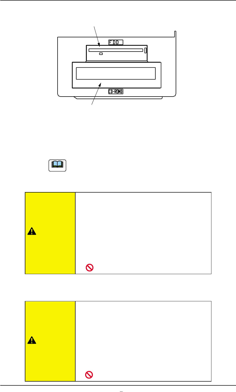
2.3.8 Service Panel
Fig. 1A18
*1 Floppy Disk Drive
The floppy disk drive is used to write data such as the device data,
a pattern program on a floppy disk (FD). The data on the floppy disk
can also be loaded onto the machine.
Do not press the eject button of the disk drive when the
access lamp is ON. Otherwise, the data stored on the in-
serted floppy disk may be corrupted, causing a mechanical
breakdown.
• Do not use the floppy disk drive for any func-
tions other than the specified ones.
Otherwise, the machine may break down because
the program in the hard disk may be changed due
to computer viruses or worms.
• Do not press the eject button of the disk drive
when the access lamp is ON.
Otherwise, the data may be corrupted, causing the
machine to break down.
*2 CD-ROM Drive
This is a device that can only read information from CD-ROM disk.
This is used to upgrade the system program.
• Do not use any CDs other than the provided
ones.
Otherwise, the machine may break down because
the program in the hard disk may be changed due
to computer viruses or worms.
• Do not remove the inserted CD from the drive
while the lamp is "ON".
Otherwise, the data may be corrupted, causing the
machine to break down.
*1 Floppy Disk Drive
*2 CD-ROM Drive
2.3 Equipment for Operations
Note
CAUTION
CAUTION
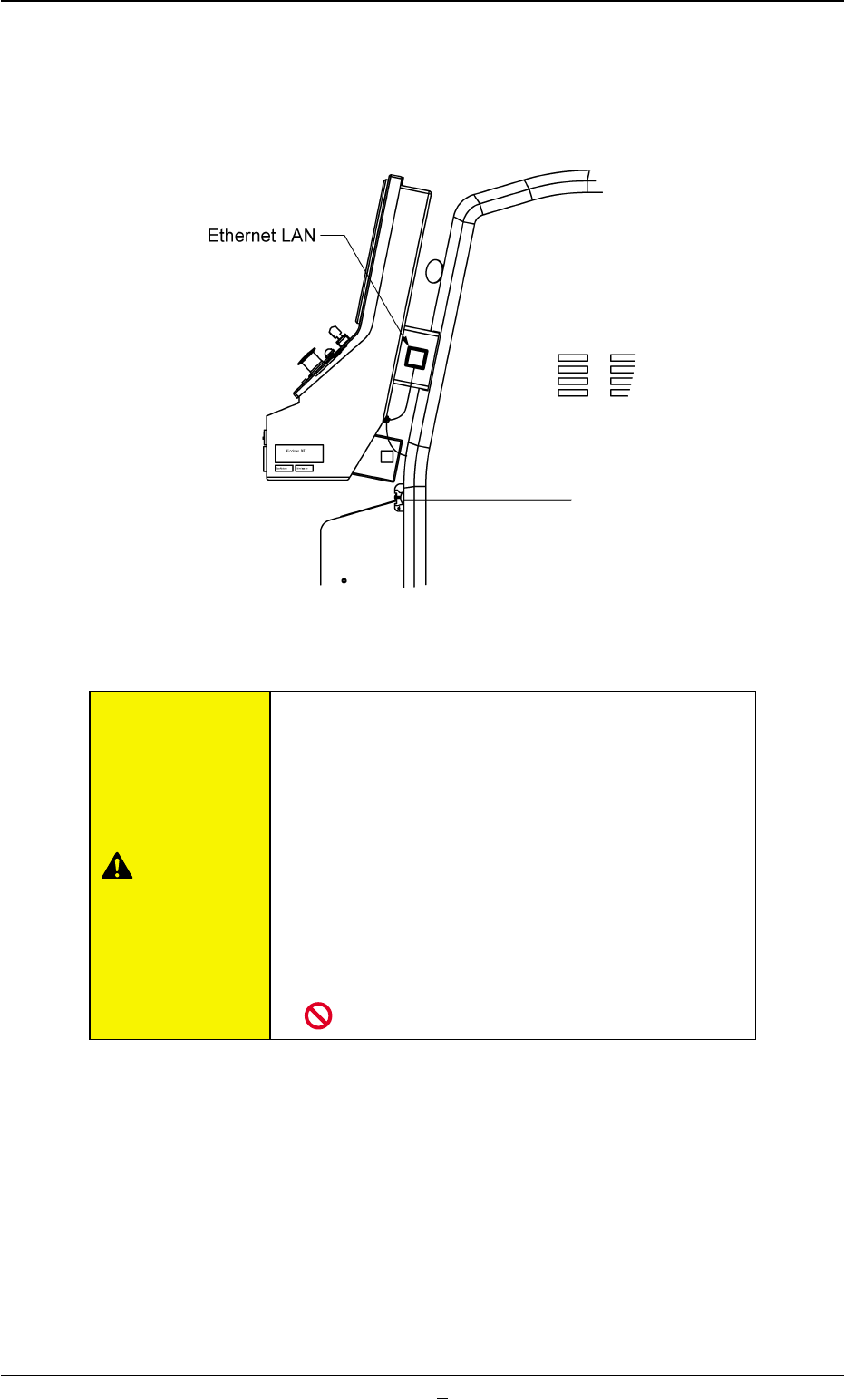
2.3.9 Ethernet LAN
Data can be exchanged between the network terminal (option) and the
machine in the Ethernet LAN system.
Fig. 1A18-1 Side View of Front Operation Panel
• Do not exchange data through Ethernet cabling
(Local Area Network) between the system and
a computer that is not provided with any viral
strategies.
Otherwise, viruses might enter the network, caus-
ing the machine to malfunction.
• Isolate the system, using Ethernet cabling (Lo-
cal Area Network) except for the specified func-
tional operations.
Otherwise, the machine will break down.
2.3 Equipment for Operations
0308-003 1-24-1 AHB01EOPP
CAUTION
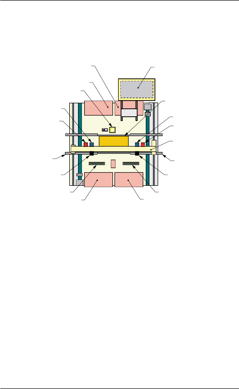
2.4 Main Units
2.4.1 Location of Main Units
Fig. 1A18-2 Location of Main Units (Provided with Multi-Layer Tray Feeder #2)
2.4 Main Units
Front Side of Machine
Rear Side of Machine
Feeder Base #2
(Option)
Feeder Base #1
Fixed Camera A1
Head #2
P.E.C. Recognition
Camera 2
L Conveyor
Movable Camera 2
Nozzle Stocker B2
Feeder Base #4
Multi-Layer Tray Feeder #2
(Option)
P.C.B. Positioning Section
(P Conveyor)
Head #1
P.E.C. Recognition
Camera 1
X/Y Beam
R Conveyor
Movable Camera 1
Nozzle Stocker B1
Feeder Base #3
0206-003 1-25 AHB01EOPP