1OM-1075-002.pdf - 第84页
3 . 2 Component Picks and Placement Component Picks Components are picked up from the feeder by the vacuum nozzles on the placement heads. Fig. 1A39 T ape Feeder Component Placement The components picked up by the vacuum…
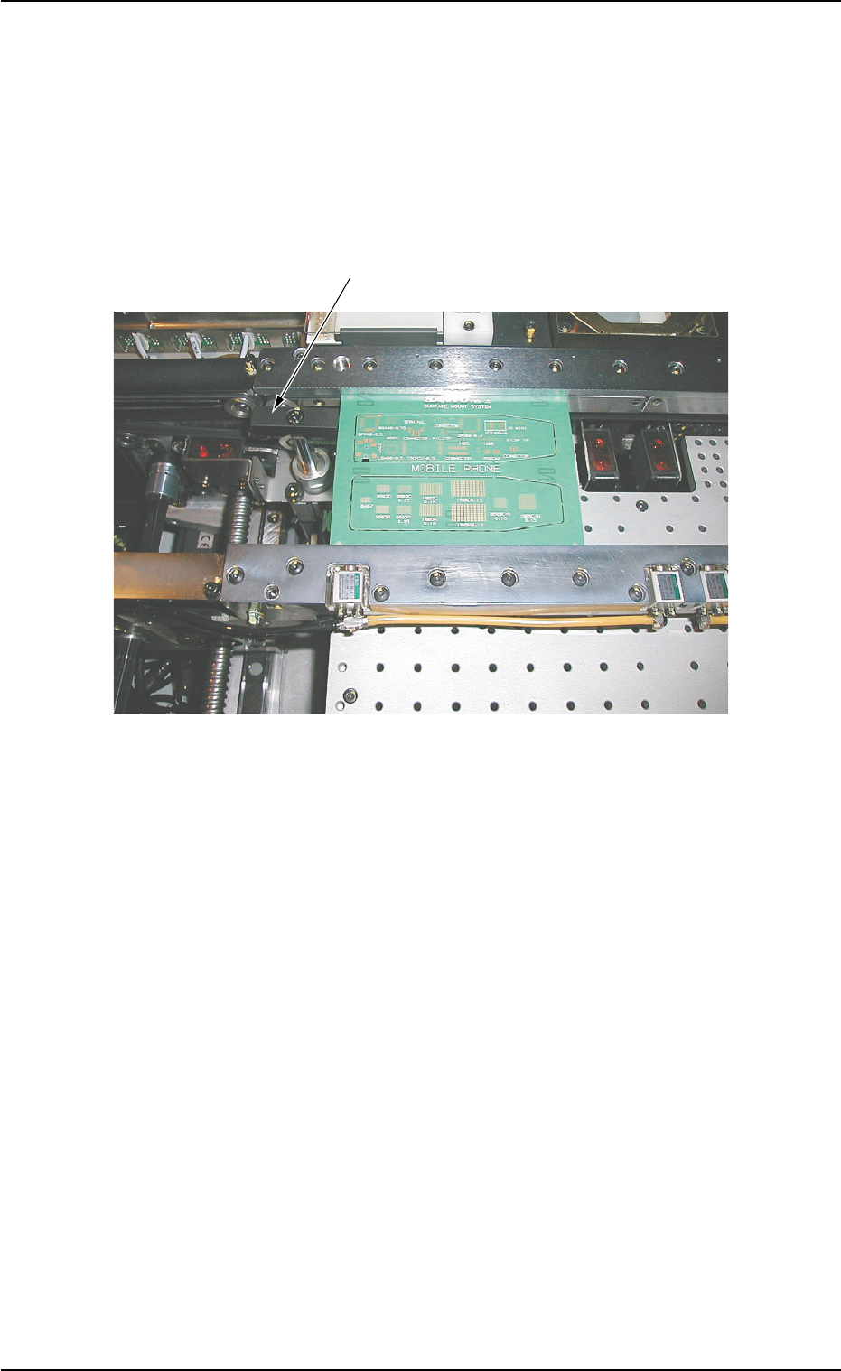
P.C.B. Positioning (Placement Coordinate Reference)
P.C.B. Stopper P1 descends and the P.C.B. which has moved to
the P.C.B. positioning section from the standby position makes a
U-turn just before it reaches P.C.B. Stopper P2 and is stopped by
P.C.B. Stopper P1 that has already ascended.
The P.C.B. is held firmly by the clamping plate on the P.C.B. posi-
tioning section.
Fig. 1A38 P.C.B. Positioning (Placement Coordinate Reference)
P.C.B. Stopper P1
3.1 P.C.B. Transfer and Positioning
0206-002 1-37 AHB01EOPP
3.2 Component Picks and Placement
Component Picks
Components are picked up from the feeder by the vacuum nozzles
on the placement heads.
Fig. 1A39 Tape Feeder
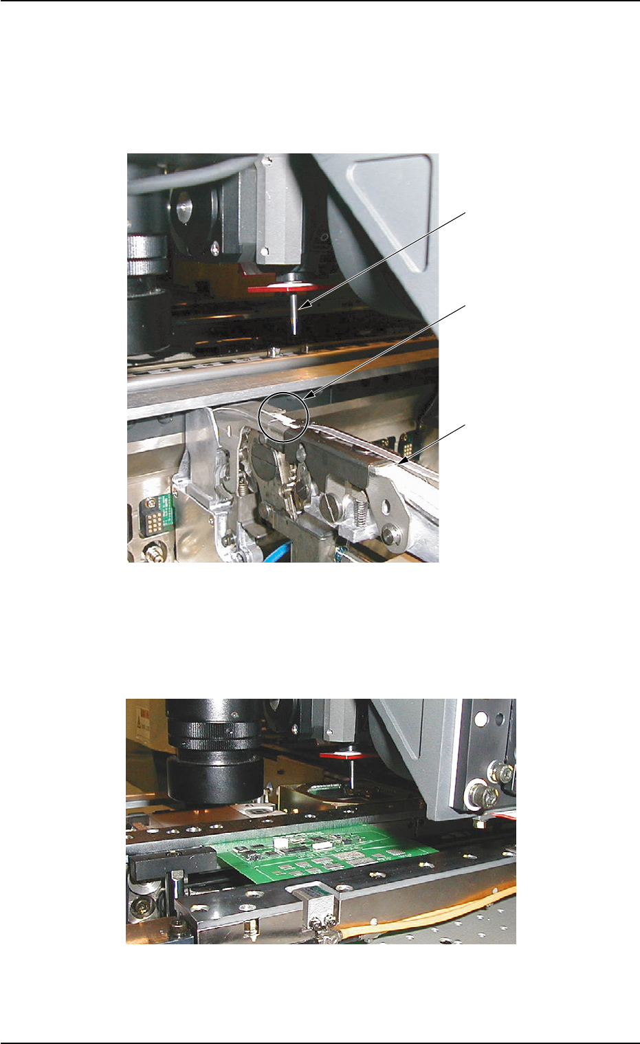
Component Placement
The components picked up by the vacuum nozzles are placed on
the P.C.B. (standby mode) in the P.C.B. positioning section.
Fig. 1A40 P.C.B. Positioning Section
Vacuum Nozzle
Pick-Up Position
Tape Feeder
3.2 Component Picks and Placement
01 12-001 1-38 AHB01EOPP
3.2 Component Picks and Placement
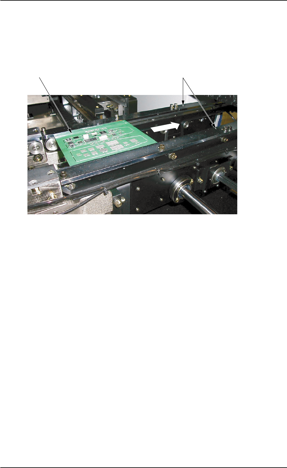
3.3 P.C.B. Transfer (to the output machine)
After all required components are placed on the P.C.B. and the P.C.B. is
kept clear of Stopper P2 that has descended, it is transferred to the R
conveyor and carried further to the output machine.
Fig. 1A41 R Conveyor
P.C.B.
R Conveyor
Onput Machine
01 12-001 1-39 AHB01EOPP