1OM-1075-002.pdf - 第77页
Do not touch the placement heads by hand because a strong motor is used to move them at high speed. Otherwise, you may be trapped in the moving mechanism, causing a major injury . • Keep the diffusion plates of the vacuu…
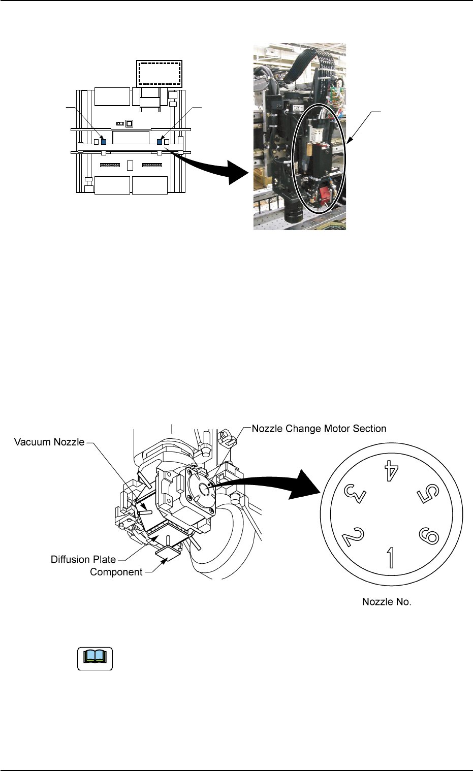
2.4.6 Placement Head Section
Fig. 1A28
The placement head section is provided with a mechanism that places
the component picked by a vacuum nozzle on the P.C.B.
The X/Y beam has two placement heads.
Each head has 6 fitting holes for nozzles. Up to 6 types of vacuum
nozzles can be attached to each head.
6 types of nozzles are shifted by rotation in the nozzle change motor
section.
Fig. 1A29
Refer to "4. Vacuum Nozzle Types" in "Section 1" of "Vol. 2" for
the standard nozzles.
Placement
Head Section
Head #1
Head #2
Rear Side of Machine
Front Side of Machine
(Top View)
(Rough View)
0206-003 1-30 AHB01EOPP
Note
2.4 Main Units
Do not touch the placement heads by hand because
a strong motor is used to move them at high speed.
Otherwise, you may be trapped in the moving
mechanism, causing a major injury.
• Keep the diffusion plates of the vacuum nozzles
clear of oil, nicks, etc. Otherwise, an error may oc-
cur during component recognition.
• Do not bring a magnet close to any vacuum nozzle.
Otherwise, an error may occur during
component picks and placement.
• Do not touch the L-axis U/D detection fitting by hand.
Otherwise, the fitting will be deformed, making it
impossible to be zeroed.
0308-002 1-31
AHB01EOPP
2.4 Main Units
WARNING
CAUTION
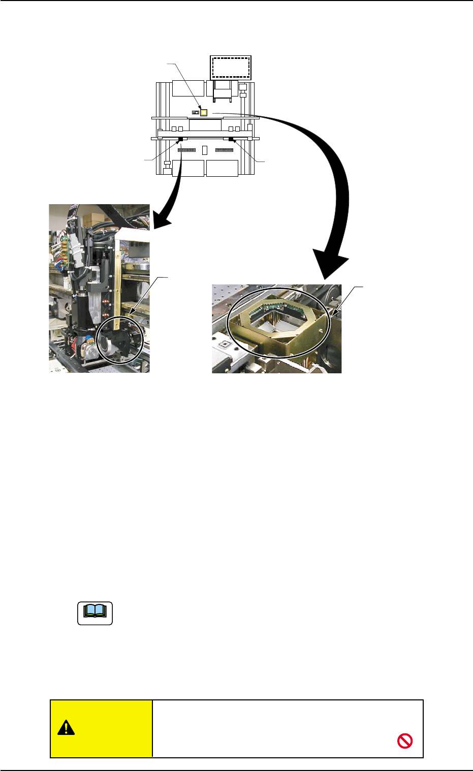
2.4.7 Component Recognition Section
Fig. 1A32
The machine is provided with a mechanism that inspects (recognizes)
the components picked up by vacuum nozzles, using three component
recognition cameras and three light sources.
Movable Cameras (2 pcs.) : Each placement head is provided with
one movable camera.
Mainly small components can be recog-
nized.
The component recognition is also pos-
sible while the X/Y beam is moving.
Fixed Camera (1 pc.) : This camera is installed beside the P.C.B.
positioning section.
Mainly large components can be recog-
nized.
The component recognition function is used to recognize the
following three items.
• Component Detection
• Inspection of Components according to the component li-
brary
• Measurement of Positional abd Angular Deviations of Com-
ponents
Do not make the protective glasses of the recognition
cameras dirty. Otherwise, the recognition
accuracy may deteriorate.
Note
0308-003 1-32 AHB01EOPP
Rear Side of Machine
Front Side of Machine
(Top View)
(Rough View)
Fixed Camera
Movable Camera
Fixed Camera A1
Movable Camera 2
Movable
Camera 1
2.4 Main Units
CAUTION