1OM-1075-002.pdf - 第38页
4.2.3 X-Axis Collision Detection Sensor This sensor is provided to detect that both heads have approached abnormally for protection of the X/Y beam. Fig. 1X41 Lower Surface of Machine Sensor Name Symbol Countermeasures X…
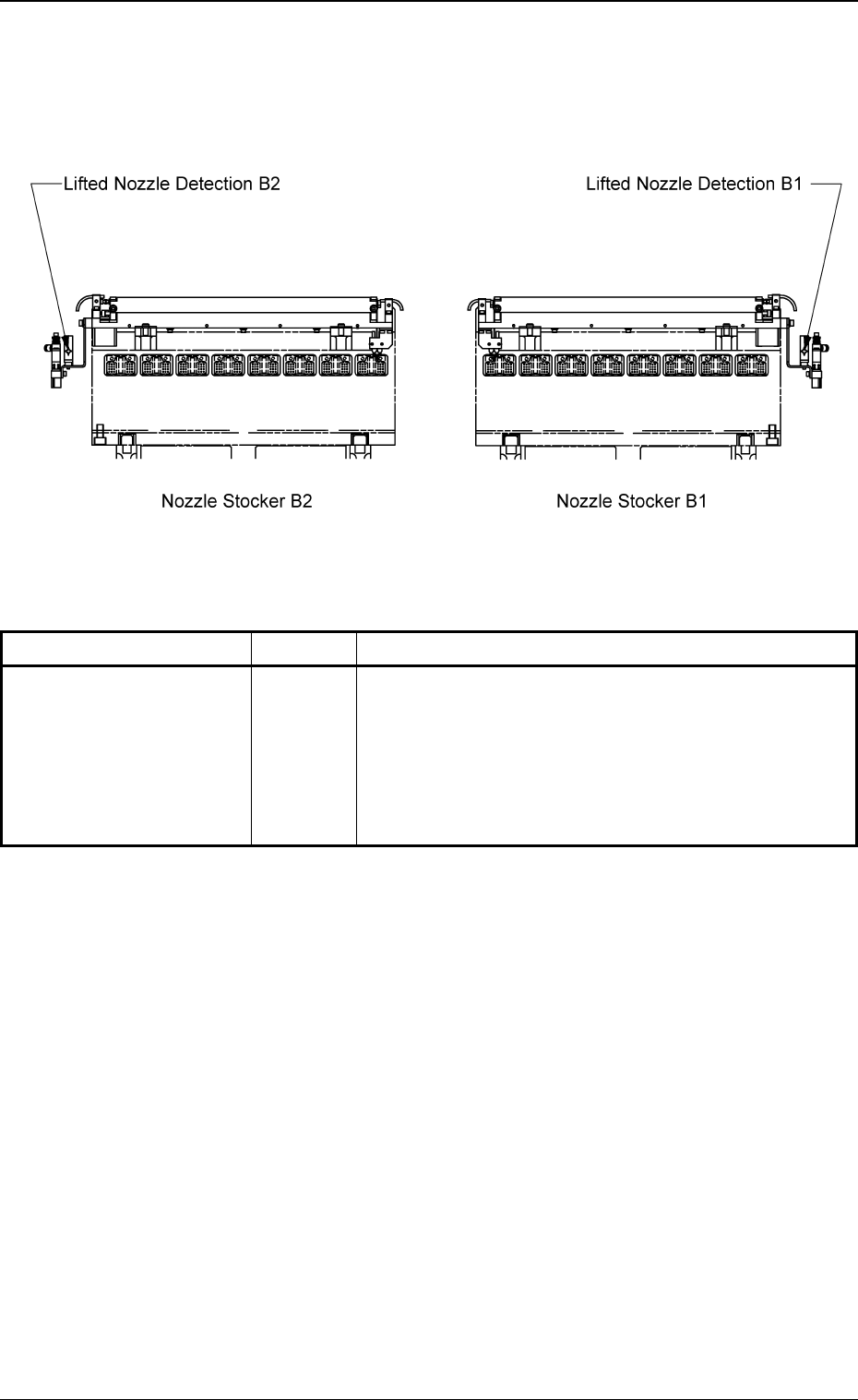
4.2.2 Lifted Nozzle Detection Sensors
These sensors are provided to protect the placement heads when a
vacuum nozzle is ejected out of the nozzle stocker.
Fig. 1X40 Front View of Machine
Sensor Name Symbol Countermeasures
Lifted Nozzle Detection B1
Lifted Nozzle Detection B2
Table 1X11
When one of these sensors is turned OFF (light emit-
ted and not received), the following measures are taken.
• The excitations of the beam X/Y axis and the nozzle
U/D axis are shut off.
(At the same time, the nozzle U/D axis is braked.)
BPH061
BPH061
0206-003 3 6
AHB01EOPP
4.2 Module Protection Sensors
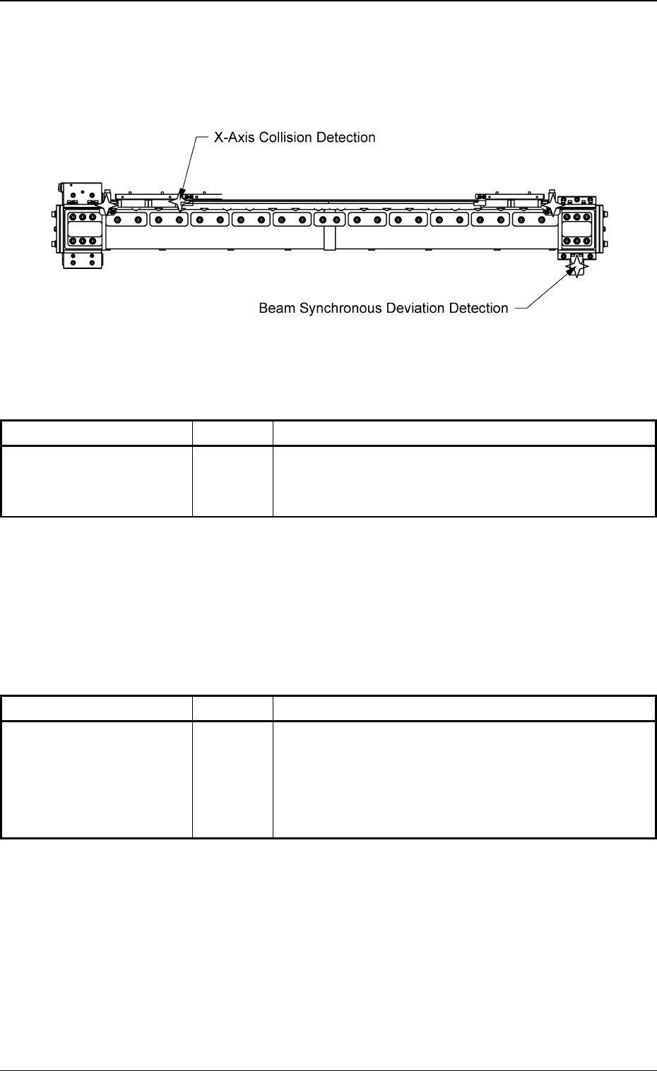
4.2.3 X-Axis Collision Detection Sensor
This sensor is provided to detect that both heads have approached
abnormally for protection of the X/Y beam.
Fig. 1X41 Lower Surface of Machine
Sensor Name Symbol Countermeasures
X-Axis Collision Detection
4.2.4 Beam Synchronous Deviation Detection Sensor
This sensor is provided to detect the deviations of both Y axes for pro-
tection of the X/Y beam.
Sensor Name Symbol Countermeasures
Beam Synchronous
Deviation Detection
4.2 Module Protection Sensors
Table 1X12
When this sensor is turned OFF (light emitted and not
received), the following measures are taken.
• Both heads stop rapidly.
BPH035
Table 1X13
When this sensor is turned OFF (light emitted and re-
ceived), the following measures are taken.
• The excitations of the beam X/Y axis and the nozzle
U/D axis are shut off.
(At the same time, the nozzle U/D axis is braked.)
BPH038
0206-002 3 7 AHB01EOPP
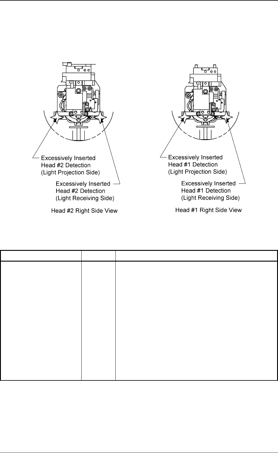
4.2.5 Excessively Inserted Nozzle Detection Sensors
These sensors are provided to protect the placement heads against
any vacuum nozzle that is excessively inserted due to an error in the
pattern program.
Fig. 1X42
Sensor Name Symbol Countermeasures
Excessively Inserted
Head #1 Detection
(Light Projecting Side)
Excessively Inserted
Head #1 Detection
(Light Receiving Side)
Excessively Inserted
Head #2 Detection
(Light Projecting Side)
Excessively Inserted
Head #2 Detection
(Light Receiving Side)
4.2 Module Protection Sensors
0206-002 3 8 AHB01EOPP
Table 1X14
When one of these sensors is turned OFF (light emit-
ted and not received), the following measures are taken.
• The excitations of the beam X/Y axis and the nozzle
U/D axis are shut off.
(At the same time, the nozzle U/D axis is braked.)
BPH025T
BPH025R
BPH025T
BPH025R