1OM-1075-002.pdf - 第119页
AHB01EOPP 1 . 5 Interruption of Automatic Operation 1.5.1 Interruption with [CANCEL] Button When the [STOP] button on the operation panel is pressed, the follow- ing "Run Mode" tab sheet appears. (1) Press the …
AHB01EOPP
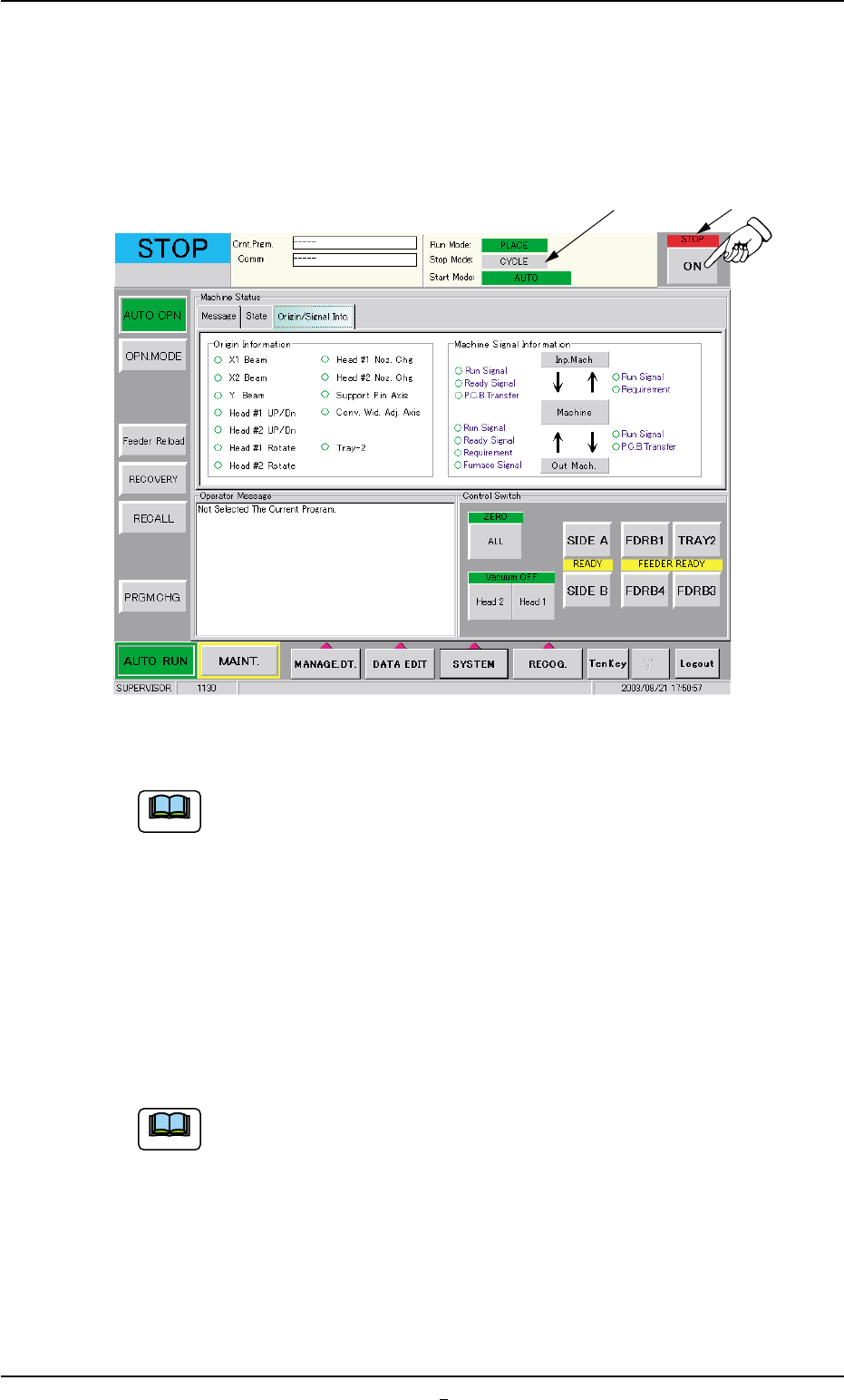
• Temporary Stop (Pause) with [ON] Button (entitled "STOP")
When "STEP" is set as "Stop Mode" (*1) and the [ON] button (*2, en-
titled "STOP") is pressed, the automatic operation stops temporarily.
Fig. 1C20-1
When "CYCLE" is set as "Stop Mode" (*1), select the [STEP]
button (entitled "STOP") in the "Run Mode" tab sheet ("OPN.
MODE" submenu window).
1.4.4 Stop Operation by Selection of "Auto Stop Mode"
Stop the input machine.
After all P.C.B.’s on the system line are processed and discharged, the
input machine automatically stops running.
(a) This function works only when "Enable" is set in the "Auto
stop mode" text box of the "P.C.B. Transfer Mode Setup"
tab sheet. (Operation Procedure: [SYSTEM] Button on Main
Menu Bar Æ [SYS DATA] Button Æ "Auto Operation" Tab
Æ "P.C.B. Transfer Mode Setup" Tab Sheet)
(b) When a machine of another brand is connected to the sys-
tem line, this function may not work.
0308-002 3-18-1
1.4 Temporary Stop and Restart of Automatic Operation
Note
Note
*2
*1
AHB01EOPP
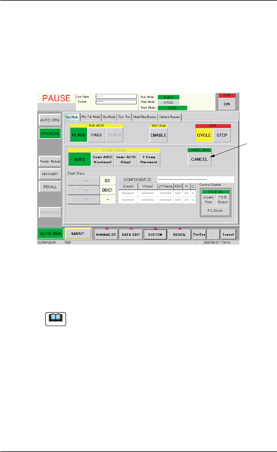
1.5 Interruption of Automatic Operation
1.5.1 Interruption with [CANCEL] Button
When the [STOP] button on the operation panel is pressed, the follow-
ing "Run Mode" tab sheet appears.
(1) Press the [STOP] button on the operation panel.
Fig. 1C21 "Run Mode" Tab Sheet ("PAUSE" Mode)
(2) When the [CANCEL] button (*1, entitled "CANCEL RUN") is pressed
after the "Run Mode" tab ("OPN. MODE" submenu window), the
automatic operation is interrupted.
To continue the automatic operation after the interruption, refer
to "Step (10)" and the subsequent items in "3.1 [EMERGENCY
STOP] Switch Pressed" in "Section 4" for details.
0308-004 3-19
1.5 Interruption of Automatic Operation
Note
*1
AHB01EOPP
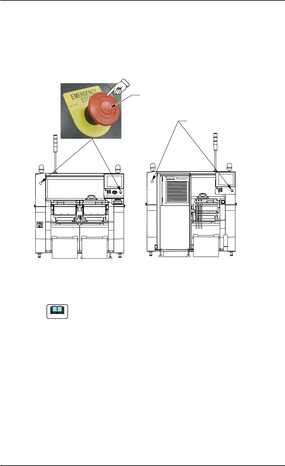
1.5.2 Interruption with [EMERGENCY STOP] Switch
Use the [EMERGENCY STOP] switch to immediately stop the machine
in an emergency.
An error alarm is issued and the LED of the [POWER ON] button illumi-
nates in red.
Fig. 1C22
Refer to "Section 4 Remedy of Simple Trouble" for the proce-
dures to reset the machine to the normal condition from an
emergency stop.
[EMERGENCY STOP] Switch
[EMERGENCY STOP]
Switches
Front Side of Machine
Rear Side of Machine
1.5 Interruption of Automatic Operation
0308-004 3-20
Note