1OM-1075-002.pdf - 第75页
2.4.5 X/Y Beam Section Fig. 1A26 The X/Y beam is provided with a mechanism that moves the placement heads. By moving the placement heads in the X and Y directions, it becomes possible to attach or detach a vacuum nozzle,…
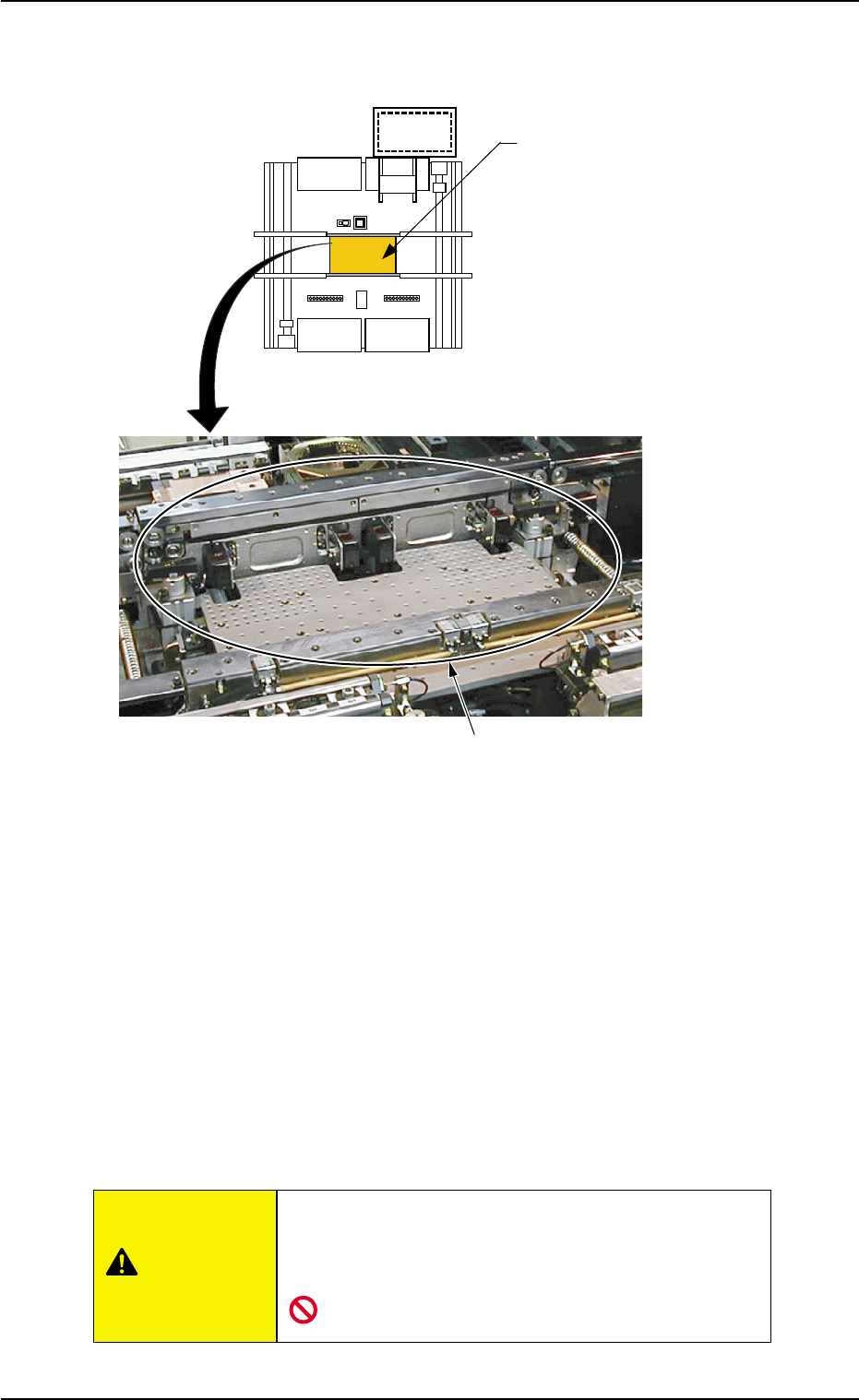
2.4.4 P.C.B. Positioning Section
Fig. 1A24
The P.C.B. positioning section is provided with a mechanism that holds
a P.C.B. (sent from the input conveyor) firmly on the P.C.B. positioning
section (P conveyor).
The placement heads move to the firmly-held P.C.B. and place the com-
ponents according to the pattern program data.
A P.C.B. positioning operation is required mainly when a program change
operation is performed.
It is necessary to re-arrange the P.C.B. support pins and set up the
conveyor width when the current pattern program (model) is changed to
another one.
Do not put any foreign substance on the P.C.B. posi-
tioning section. Otherwise, the machine will break
down.
P.C.B. Positioning Section
P.C.B. Positioning Section
(P Conveyor)
Rear Side of Machine
Front Side of Machine
(Top View)
(Rough View)
0308-003 1-28 AHB01EOPP
2.4 Main Units
CAUTION
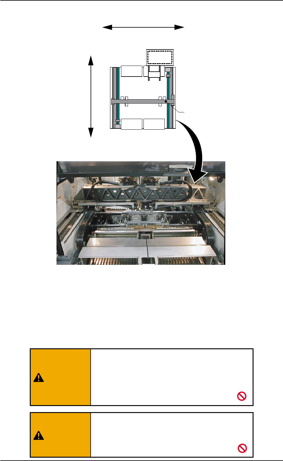
2.4.5 X/Y Beam Section
Fig. 1A26
The X/Y beam is provided with a mechanism that moves the placement
heads.
By moving the placement heads in the X and Y directions, it becomes
possible to attach or detach a vacuum nozzle, pick up a component,
and place the picked component on the P.C.B.
Those who wear implanted pacemakers are not
allowed to work inside the carriage covers.
A strong magnet is used in the X/Y beam section.
Otherwise, a pacemaker may be affected by the
magnetism and a serious accident will result.
Do not touch the X/Y beam by hand because a
strong motor is used to move the beam at high speed.
Otherwise, you may be trapped in the moving
mechanism, causing a major injury.
X/Y Beam
X Direction
Y Direction
Rear Side of Machine
Front Side of Machine
(Top View)
(Rough View)
0308-003 1-29 AHB01EOPP
2.4 Main Units
WARNING
WARNING
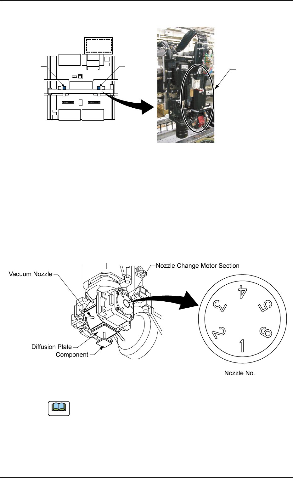
2.4.6 Placement Head Section
Fig. 1A28
The placement head section is provided with a mechanism that places
the component picked by a vacuum nozzle on the P.C.B.
The X/Y beam has two placement heads.
Each head has 6 fitting holes for nozzles. Up to 6 types of vacuum
nozzles can be attached to each head.
6 types of nozzles are shifted by rotation in the nozzle change motor
section.
Fig. 1A29
Refer to "4. Vacuum Nozzle Types" in "Section 1" of "Vol. 2" for
the standard nozzles.
Placement
Head Section
Head #1
Head #2
Rear Side of Machine
Front Side of Machine
(Top View)
(Rough View)
0206-003 1-30 AHB01EOPP
Note
2.4 Main Units