1OM-1075-002.pdf - 第85页
3.2 Component Picks and Placement 3 . 3 P .C.B. T ransfer (to the output machine) After all required components are placed on the P .C.B. and the P .C.B. is kept clear of Stopper P2 that has descended, it is transferred …
3.2 Component Picks and Placement
Component Picks
Components are picked up from the feeder by the vacuum nozzles
on the placement heads.
Fig. 1A39 Tape Feeder
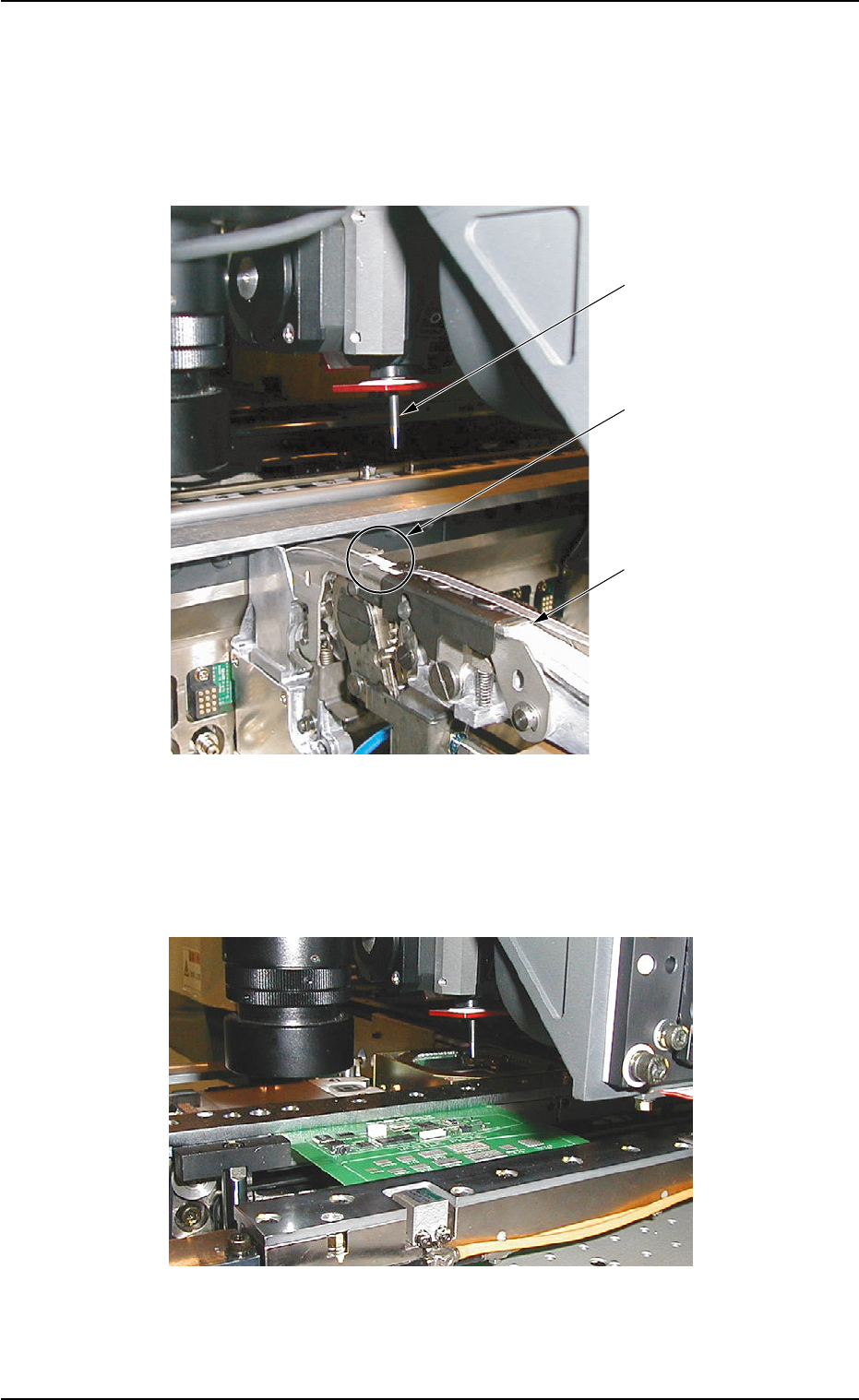
Component Placement
The components picked up by the vacuum nozzles are placed on
the P.C.B. (standby mode) in the P.C.B. positioning section.
Fig. 1A40 P.C.B. Positioning Section
Vacuum Nozzle
Pick-Up Position
Tape Feeder
3.2 Component Picks and Placement
01 12-001 1-38 AHB01EOPP
3.2 Component Picks and Placement
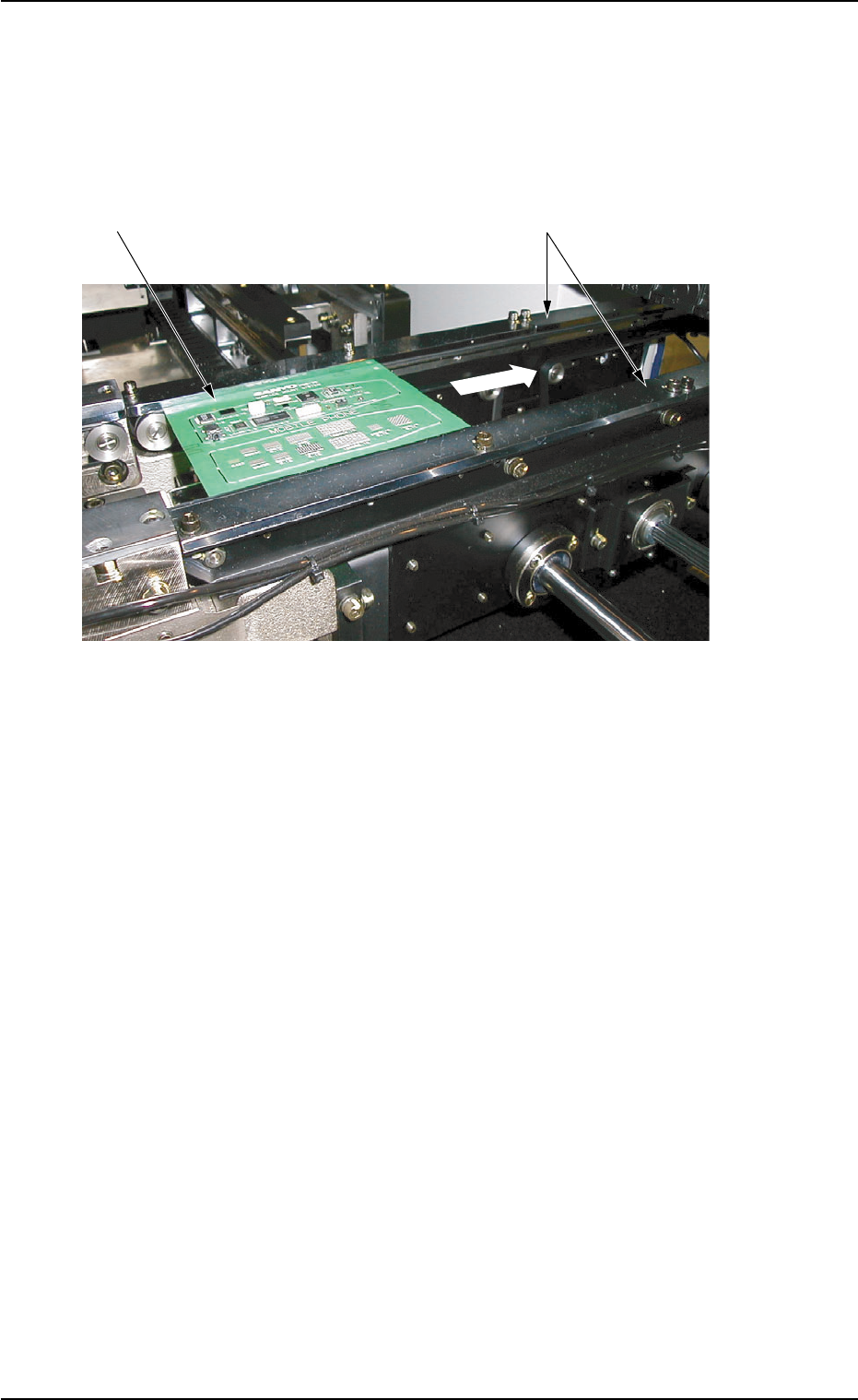
3.3 P.C.B. Transfer (to the output machine)
After all required components are placed on the P.C.B. and the P.C.B. is
kept clear of Stopper P2 that has descended, it is transferred to the R
conveyor and carried further to the output machine.
Fig. 1A41 R Conveyor
P.C.B.
R Conveyor
Onput Machine
01 12-001 1-39 AHB01EOPP

Section 2
Basic Knowledge of Operation
0308-002 2-A AHB01EOPP
This section describes the basic items to be understood for
proper machine operations.