SYS-CP842-1.1E.pdf - 第111页
3.Machine System SYS-CP842-1.1E 102 CP-842E / CP-842ME System Reference Body Data Editing Screen Body data can be edited from this scre en. For body data d eta ils, refer to the SMD Operation Manual. Push the START butto…
SYS-CP842-1.1E 3.Machine System
CP-842E / CP-842ME System Reference 101
Screen Button Explanations
Editing Operations
The following editing operations can be performed at this screen.
A. [Sequence No.]: Switches to the sequence search screen.
B. [Max. Nozzle Size]: Changes the maximum nozzle size (PENNMA) which is
specified in the production program’s part shape data
(ENVDT).
C. [Min. Nozzle Size]: Changes the minimum nozzle size (PENNMI) which is
specified in the production program’s part shape data
(ENVDT).
D. [Backlight Size]: Changes the nozzle minimum backlight size (PENBLM)
which is specified in the production program’s part shape
data (ENVDT).
E. [Enable] (Automatic
pickup position
correction):
Changes the automatic pickup point offset function setting
(PTPCRAPO) which is specified in the production
program’s part shape data (CARRING) to “0: Enable”
F. [Disable] (Automatic
pickup position
correction):
Changes the automatic pickup point offset function setting
(PTPCRAPO) which is specified in the production
program’s part shape data (CARRING) to “1: Disable”
G. [Set] (Part pickup
check):
Changes the part pickup check mode (PTPCRPCK)
which is specified in the production program’s part shape
data (CARRING).
H. [Close]: Returns to the production program editing screen.
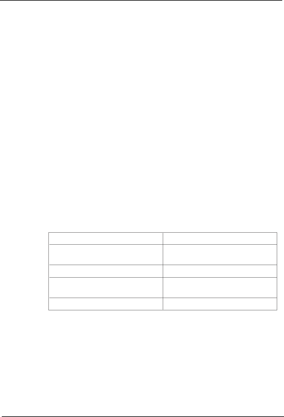
Desired Action
Change the placement nozzle.
Editing Operation
Edit the maximum and minimum nozzle size
values.
Change the placement nozzle.
Edit the backlight size.
Change the "automatic pickup position
correction" function setting.
Edit the "automatic pickup position correction"
function setting.
Change the "part pickup check" setting.
Edit the "part pickup check" setting.
T005E
3.Machine System SYS-CP842-1.1E
102 CP-842E / CP-842ME System Reference
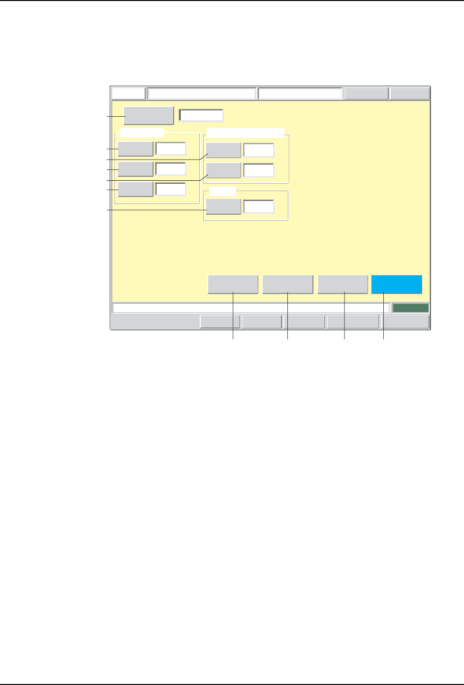
Body Data Editing Screen
Body data can be edited from this screen. For body data details, refer to the SMD
Operation Manual.
Push the START button.
FUJI
ErrorOperator
JOG:X Y CAM
Servo CountGEMCCD Monitor
Body Data Editor
FUJI_CP7_2001
Front
Close
Lead
Element
Vision Type
Sequence Number
Size Data
Parts
Height
0.9000
Body
Length Y
2.0000
[mm]
1.2500
Body
Length X
[mm]
[mm]
0.1000
Check Tolerance Values
Length X
Length Y
0.1000
[mm]
[mm]
Lead
0
Detection
Tolerance
[%]
Set Switch
123
CP7S2018E
A
B
C
D
KH I J
E
F
G

SYS-CP842-1.1E 3.Machine System
CP-842E / CP-842ME System Reference 103
Screen Button Explanations
Editing Operations
The following editing operations can be performed at this screen.
A. [Sequence No.]: Switches to the sequence search screen.
B. [Body Length X]: Changes the body’s X-direction length (PTPSZBX)
which is specified in the production program’s part
shape data (PRTFORM).
C. [Body Length Y]: Changes the Body’s Y-direction length (PTPSZBY)
which is specified in the production program’s part
shape data (PRTFORM).
D. [Part Height]: Changes the part height (including leads)
(PTPMNH) which is specified in the production
program’s part shape data (PRTFORM).
E. [Length X] (Check tolerance): Changes the body size’s X-direction tolerance
(PTPTLBX) which is specified in the production
program’s part shape data (TOLEINF).
F. [Length Y] (Check tolerance): Changes the body size’s Y-direction tolerance
(PTPTLBY) which is specified in the production
program’s part shape data (TOLEINF).
G. [Detection Count Tolerance]: Changes the lead detection count tolerance
(PTPTLCL) which is specified in the production
program’s part shape data (TOLEINF).
H. [Vision Type]: Switches to the vision type editing screen.
I. [Element]: Switches to the element data editing screen.
J. [Lead]: Switches to the lead data editing screen.
K. [Close]: Returns to the production program editing screen.
Problem
Panel's part pattern size differs from the wire
frame size. Or, a vision processing error
occurs during test placement.
Editing Operation
If the part size is incorrect, edit the body
length X and Y values.
A part height error occurs during test
placement.
Error code: 0x12040410
A part height which differs from that
specified in part data was detected.
If the part height is incorrect, edit the part
height value.
A vision processing error occurs during test
placement.
Edit the check tolerance X and Y length
values, and the lead detection count
tolerance value.
T006E