SYS-CP842-1.1E.pdf - 第83页
3.Machine System SYS-CP842-1.1E 74 CP-842E / CP-842ME System Reference Display when [ 16 Divi sion ] is selected CP7S2026E H10 N2 H10 N2 H14 N2 H14 N2 H2 N2 H2 N2 H6 N2 H6 N2 H1 1 N2 H1 1 N2 H15 N2 H15 N2 H3 N2 H3 N2 H7 …
SYS-CP842-1.1E 3.Machine System
CP-842E / CP-842ME System Reference 73
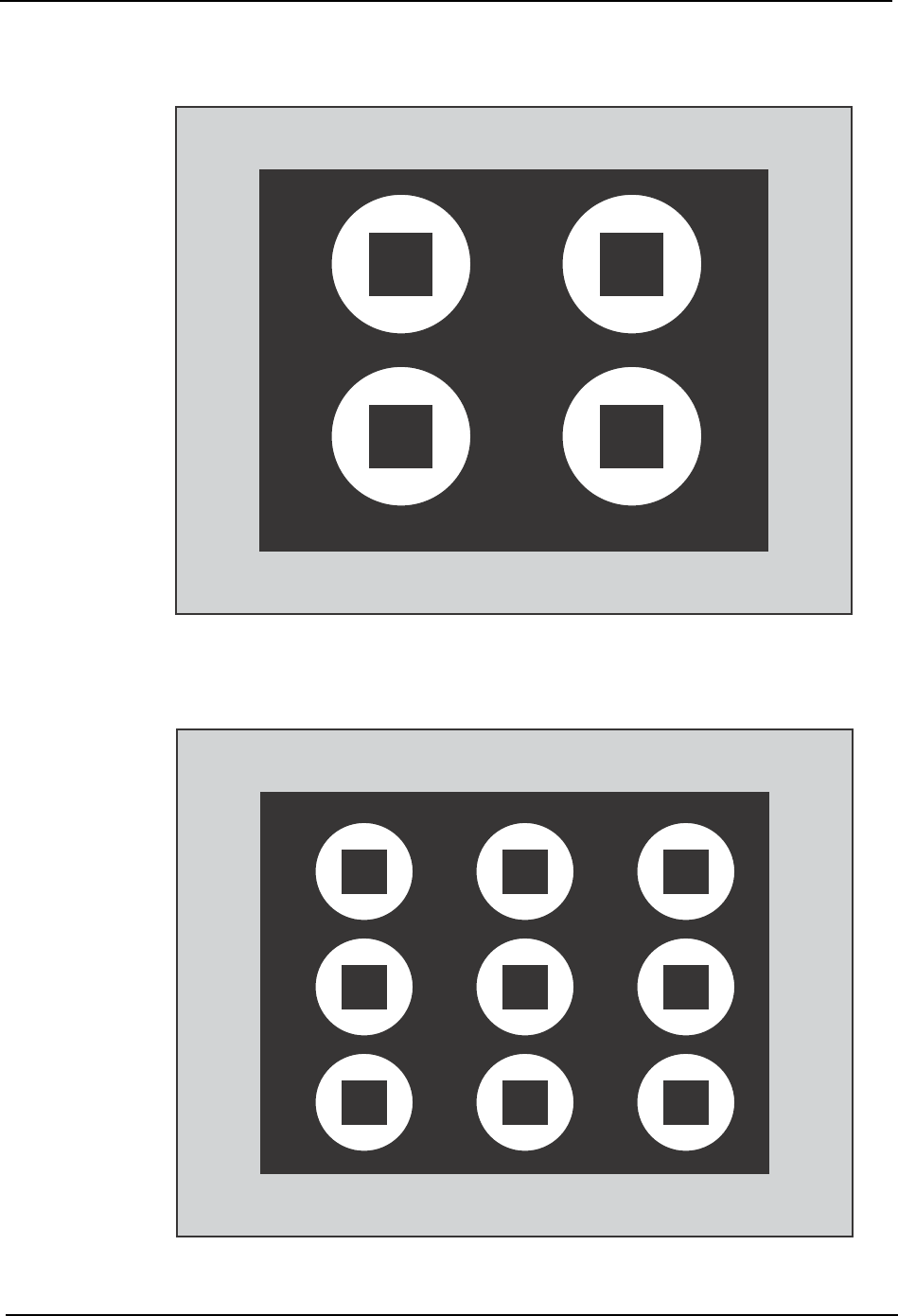
Display when [ 4 Division ] is selected
Display when [ 9 Division ] is selected
>>
H8 N2 H9 N2
H6 N2 H7 N2
CP7S2024E
CP7S2025E
H1 N2
H1 N2
H4 N2
H4 N2
H7 N2
H7 N2
H2 N2
H2 N2
H5 N2
H5 N2
>>
>>
H8 N2
H8 N2
H3 N2
H3 N2
H6 N2
H6 N2
H9 N2
H9 N2
H1 N2
H4 N2
H7 N2
H2 N2
H5 N2
>>
H8 N2
H3 N2
H6 N2
H9 N2
3.Machine System SYS-CP842-1.1E
74 CP-842E / CP-842ME System Reference
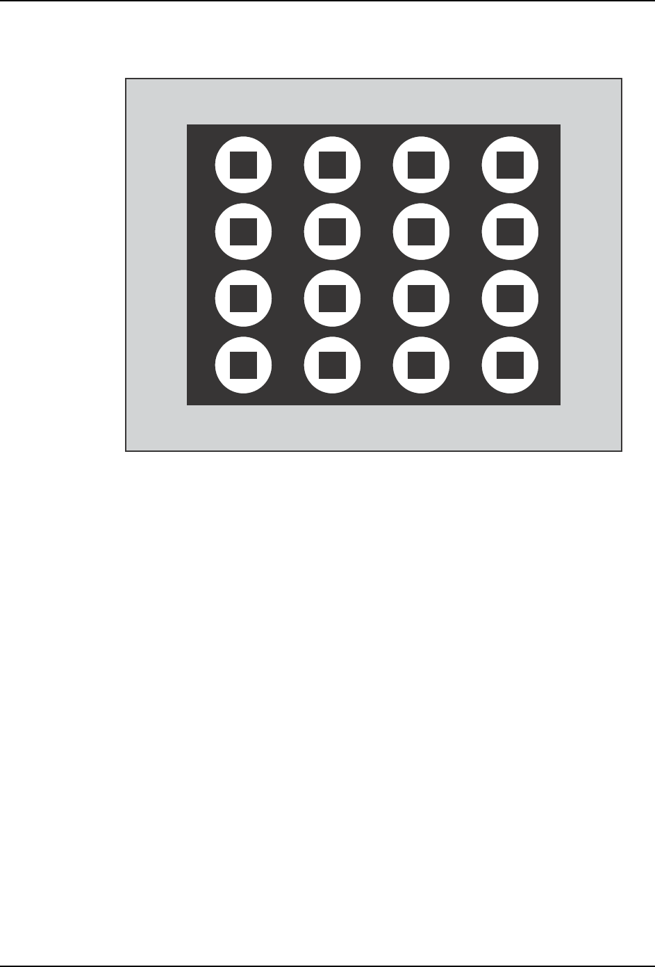
Display when [ 16 Division ] is selected
CP7S2026E
H10 N2
H10 N2
H14 N2
H14 N2
H2 N2
H2 N2
H6 N2
H6 N2
H11 N2
H11 N2
H15 N2
H15 N2
H3 N2
H3 N2
H7 N2
H7 N2
H12 N2
H12 N2
H0 N2
H0 N2
H4 N2
H4 N2
>>
>>
H8 N2
H8 N2
H13 N2
H13 N2
H1 N2
H1 N2
H5 N2
H5 N2
H9 N2
H9 N2
H10 N2
H14 N2
H2 N2
H6 N2
H11 N2
H15 N2
H3 N2
H7 N2
H12 N2
H0 N2
H4 N2
>>
H8 N2
H13 N2
H1 N2
H5 N2
H9 N2

SYS-CP842-1.1E 3.Machine System
CP-842E / CP-842ME System Reference 75
3.2 Editing Production Programs On the Machine
3.2.1 Function Explanation
This function uses the machine’s vision processing function to check for deviations between
the panel pattern or mounted parts, and the data image (wire frame). It also allows mark
data, placement coordinates, and part data to be fine-adjusted on the machine. This
function uses “simulation” and “test placement” commands. The wire frame, and the
“simulation” and “test placement” commands are explained below.
Wire Frame
The wire frame tool provides a visual representation of the mark and part data which is
registered in a production program.
Simulation Command
Acquires an image of the part placement position without the part being placed, and
displays a wire frame representation on the monitor.
1. Fiducial mark sequence
a. The panel’s mark pattern is compared with the wire frame to check for mark pattern
errors.
b. The panel’s mark pattern is compared with the wire frame to check for reading
position deviations.
2. Block skip mark sequence
a. The panel’s mark pattern is compared with the wire frame to check for reading
position deviations.
3. Placement sequence
a. The panel pattern is compared with the wire frame to check for part placement errors.
b. The panel pattern is compared with the wire frame to check for placement position
deviations.
c. The panel pattern is compared with the wire frame to check the part placement angle.
Note: When a placement position image is acquired at a placement sequence, the placement position is
corrected based on the vision processing result from the fiducial mark reading operation.
Fiducial marks: Draws the mark shapes and displays them on the monitor.
Block skip marks: Draws the mark images based on their X,Y sizes, and displays
them on the monitor.
Placement sequence: Draws the part shape and displays it on the monitor.