SYS-CP842-1.1E.pdf - 第27页
2.The Machine SYS-CP842-1.1E 18 CP-842E / CP-842ME System Reference By using a standard PC system, many features common to PC e nvironments are now par t of Fuji’s machines. • Software upgrades delivered on CD- ROM. • Et…
SYS-CP842-1.1E 2.The Machine
CP-842E / CP-842ME System Reference 17
2. The Machine
This part provides an overview of the structure and workings of the machine, and includes
a list of the terminology used in this manual.
2.1 Machine Overview
2.1.1 Notes Regarding CP-842E/842ME Operation
Absolute encoders are used on all servo motors on the machines. Differences with other
machine types are listed below.
The harness connectors on the servo motors should not be removed. If a harness
connector is removed it will be necessary to recalibrate Proper data.
Proper data measurement is also required at the following times.
• After replacing the motor
• After removing the cable connector from between the motor and servo amp
• If the backup battery within the servo amp is dead
Zero-setting is not required.
2.1.2 Whats New About the Machine System
This machine uses a new style of interface and embedded control system which delivers a
number of benefits to our users. At Fuji, we are calling equipment using this system, ‘PCC
machines’. PCC stands for ‘personal computer controlled’.
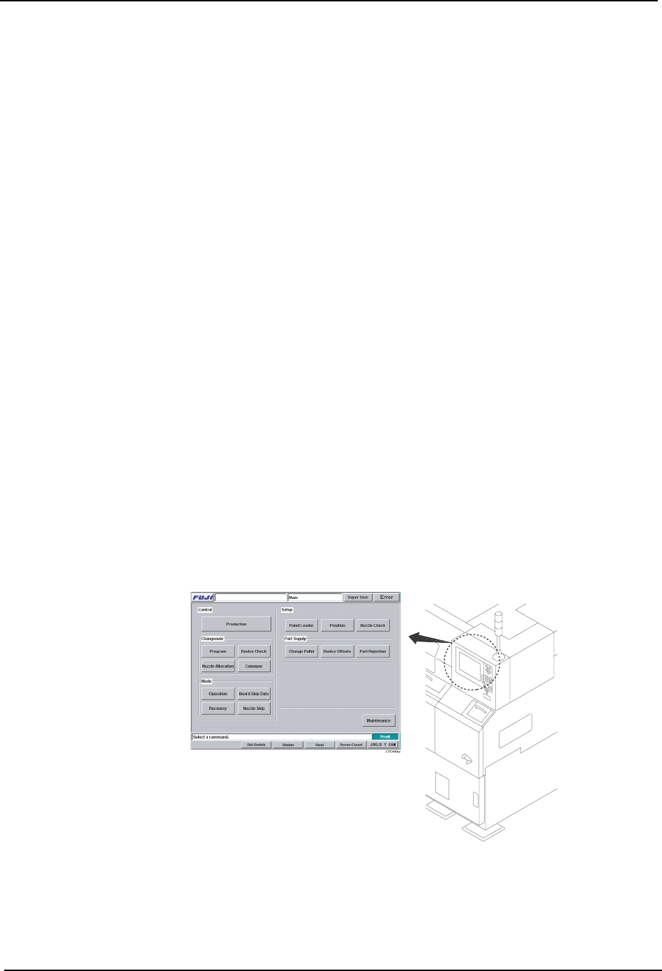
The most obvious difference from our older push button style machines is the touch panel
interface. The touch panel is a more intuitive, and easier to use for operators.
The machine control software is an application running on WindowsNTTM, installed on the
machine’s internal PC. This is connected to the touch panel, which now serves as the input/
output device for interaction with the operator.
C73OM009a
2.The Machine SYS-CP842-1.1E
18 CP-842E / CP-842ME System Reference
By using a standard PC system, many features common to PC environments are now part
of Fuji’s machines.
• Software upgrades delivered on CD-ROM.
• Ethernet networkability.
• Storage of data on hard disk.
• Incorporation of functions such as the vision system and SECS/GEM protocol, as
software running on the main system.
2.1.3 Machine Movement During Operation
The explanation below provides a description of machine movement from the point a panel
is loaded onto the in-conveyor to the point where the panel is unloaded from the out-
conveyor.
1. Panel check
When the START button is pressed, a check is made of whether a panel is present on the
conveyor.
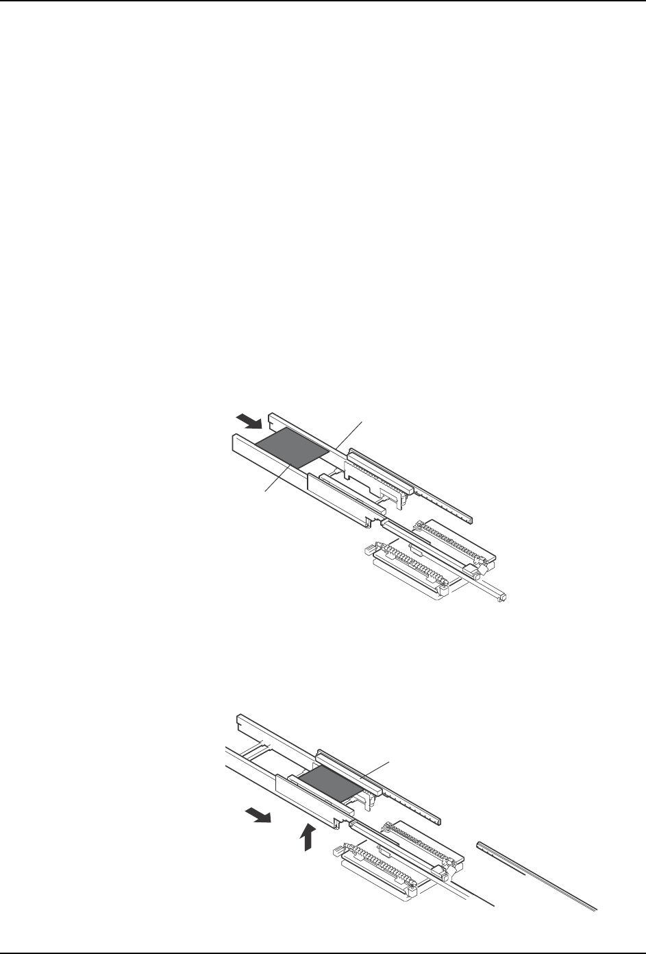
2. Panel loading
A panel is loaded onto the in-conveyor (A).
The loaded panel is then lifted and transferred to the in-carrier (B).
A
In-conveyor
Panel
B
In-carrier
SYS-CP842-1.1E 2.The Machine
CP-842E / CP-842ME System Reference 19
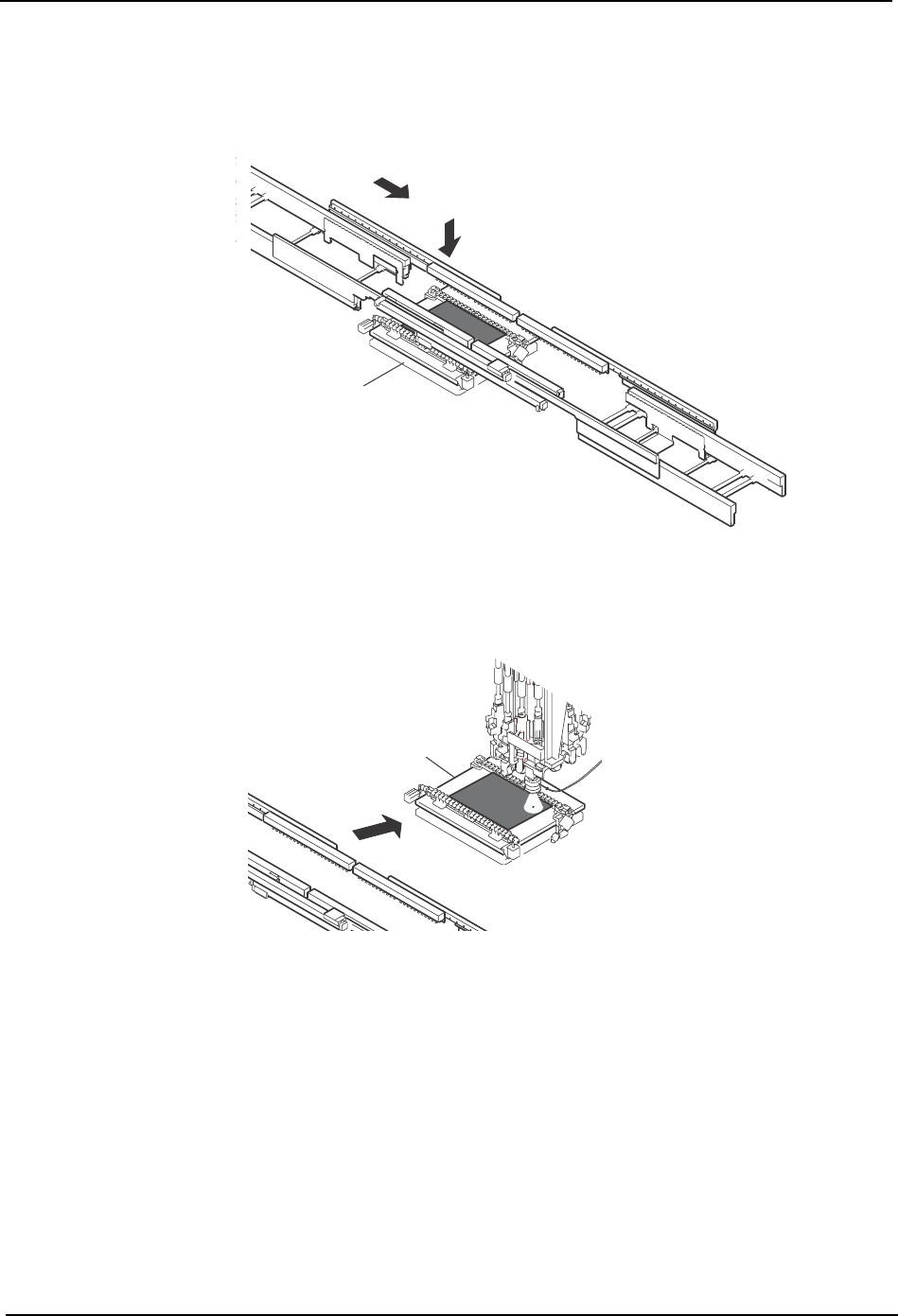
3. Advance pick-up
The machine picks up parts in advance, while the panel is transferred from the in-conveyor
to the in-carrier (C).
4. Mark reading
After the panel has been loaded onto the XY-table, the fiducial marks are read (D).
5. Nozzle change
A nozzle check is performed at Station 15 to establish which nozzle is currently down. If a
different nozzle is required for pick-up, the rotary head is indexed at station 14 until the
required nozzle is in position.
Another check is performed at Station 15 to confirm that the correct nozzle is currently down
(E).
C
XY-table
D
G
o
to
&
W
illia
m'
s
L
a
b
o
r
a
t
r
ie
s
XY-table
C7SM1001a